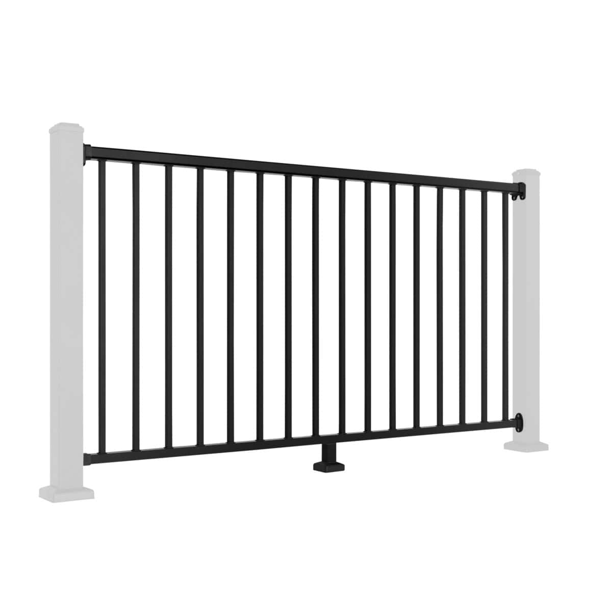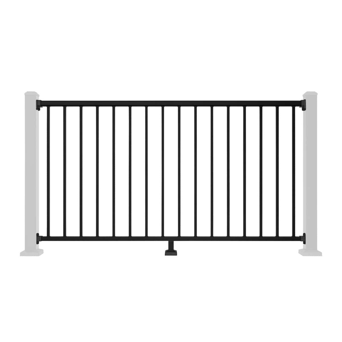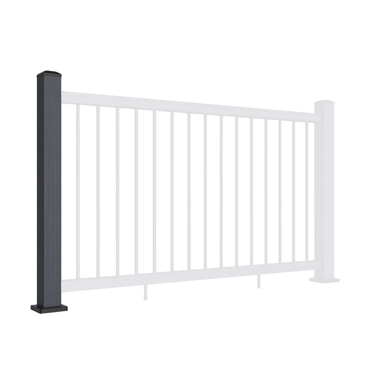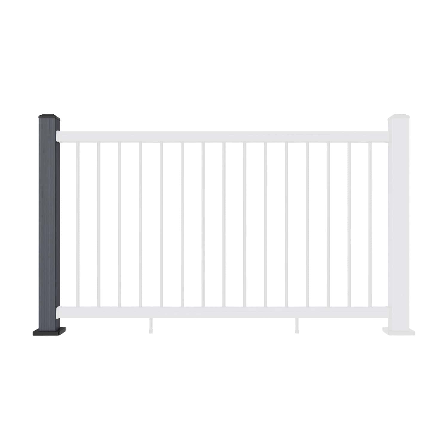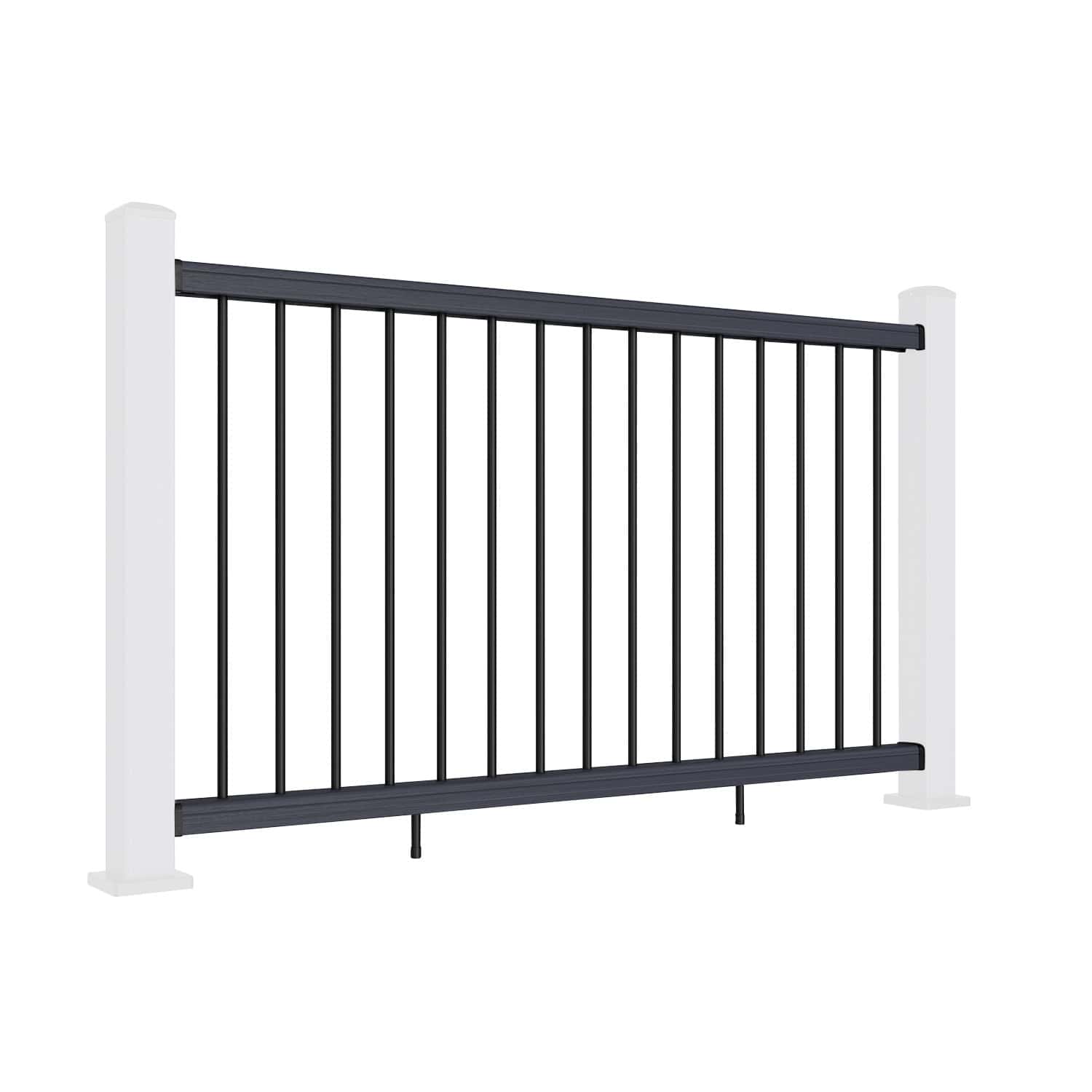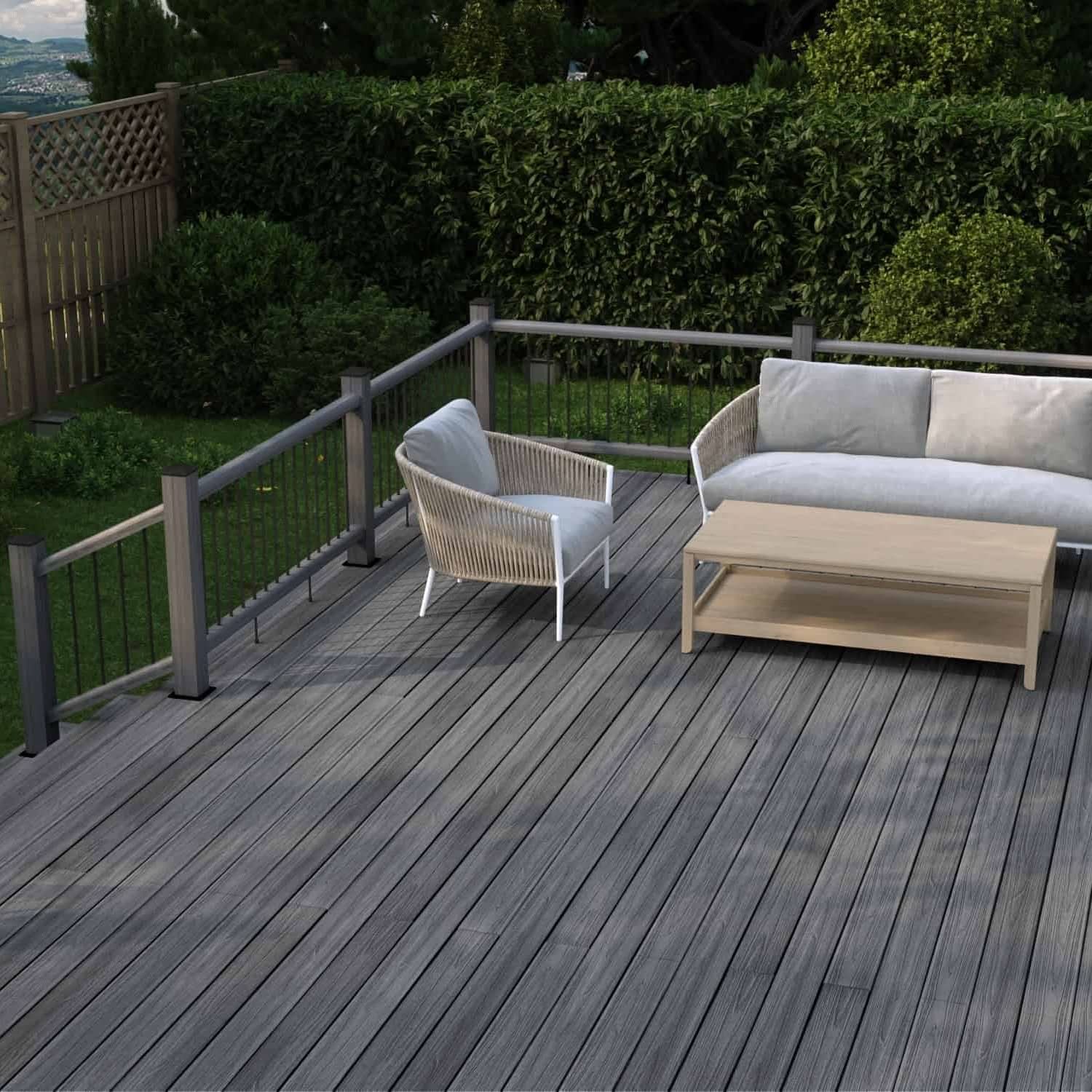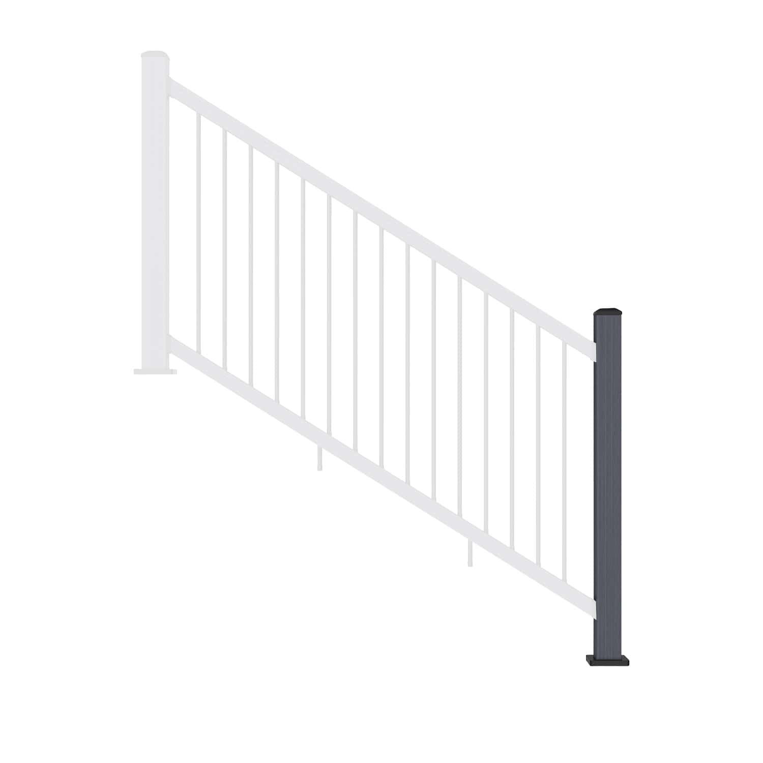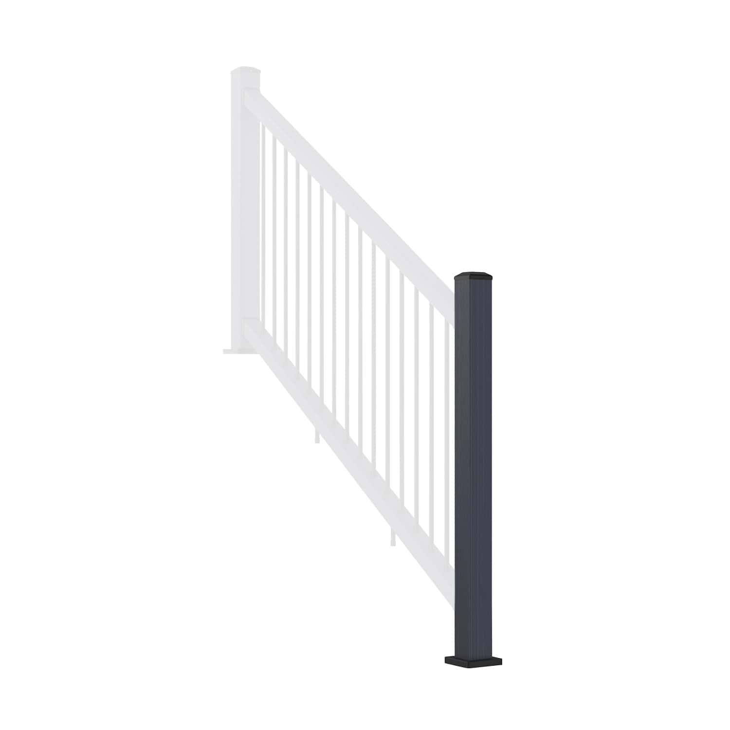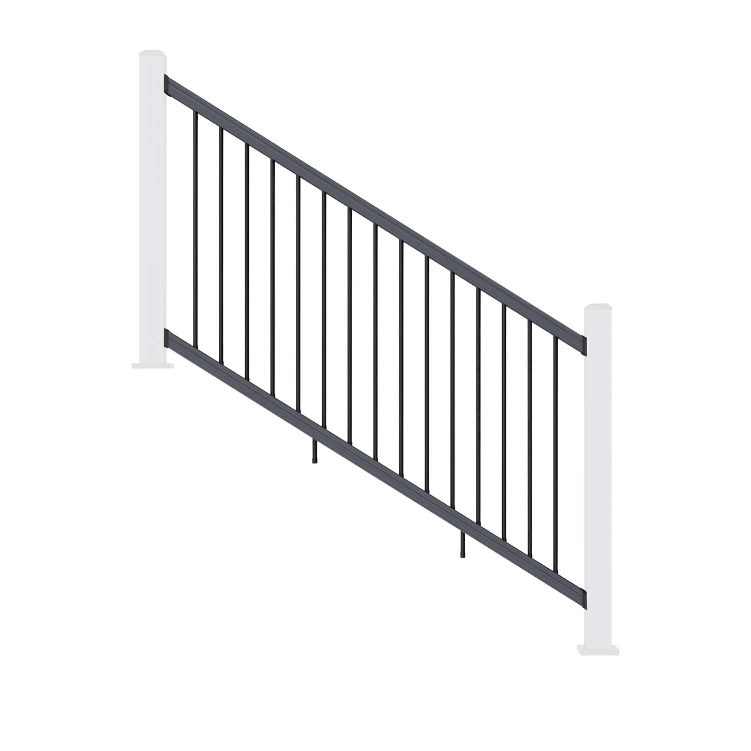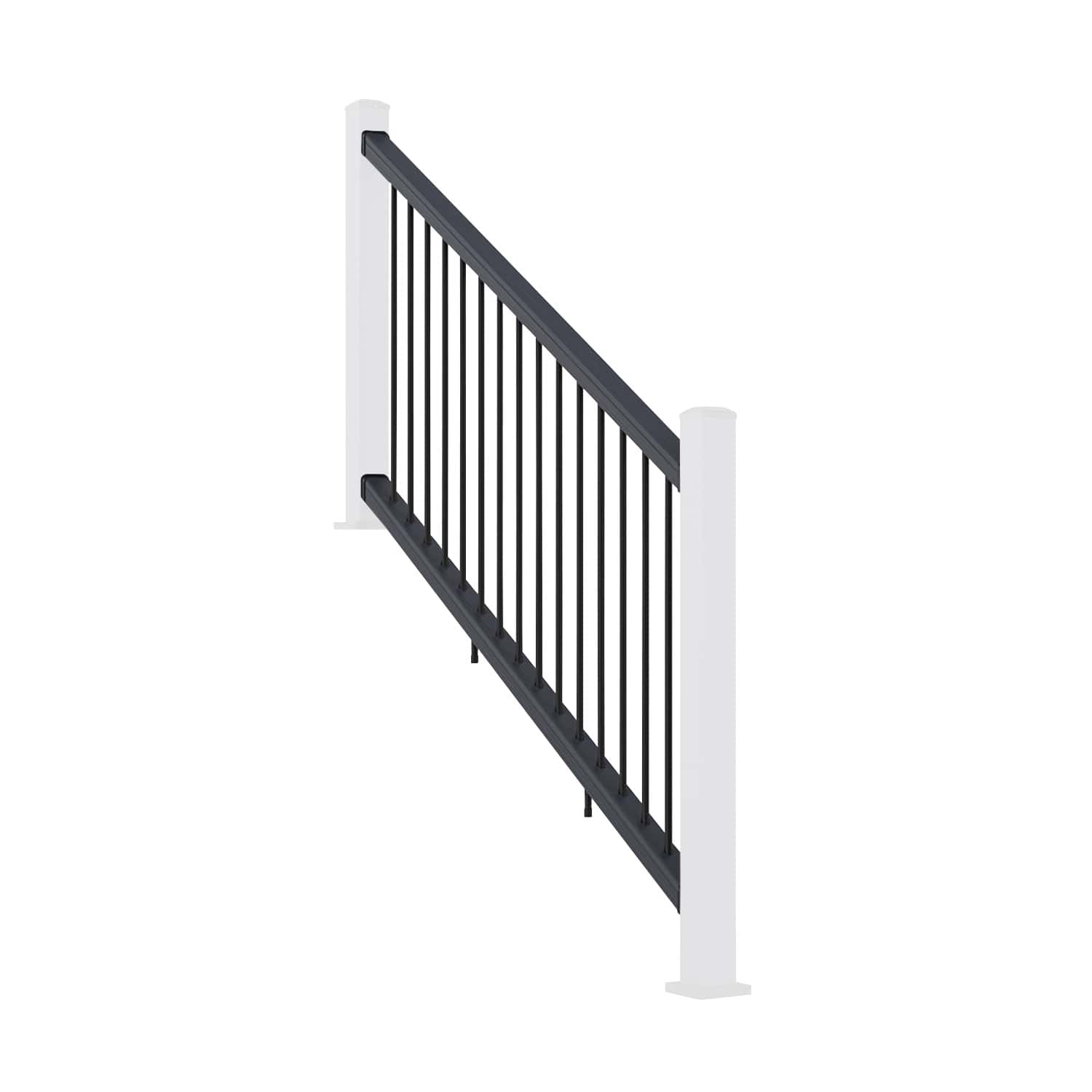

Aluminium Balustrade Glass Installation: From Rail Assembly to Final Fixings
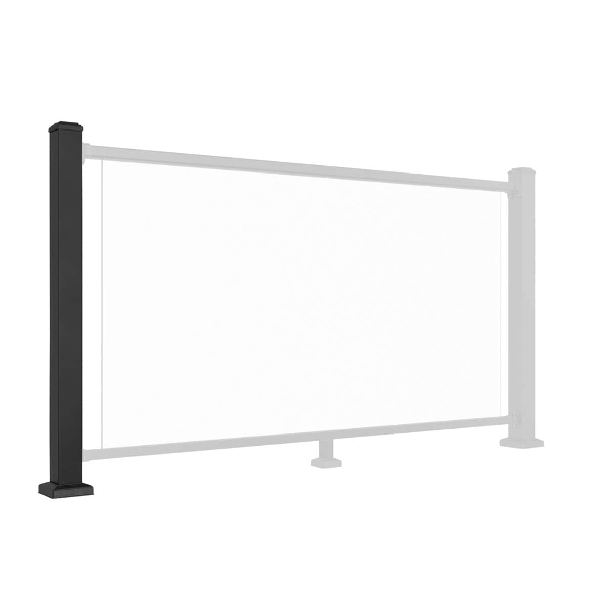
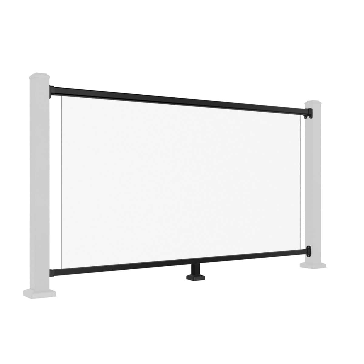
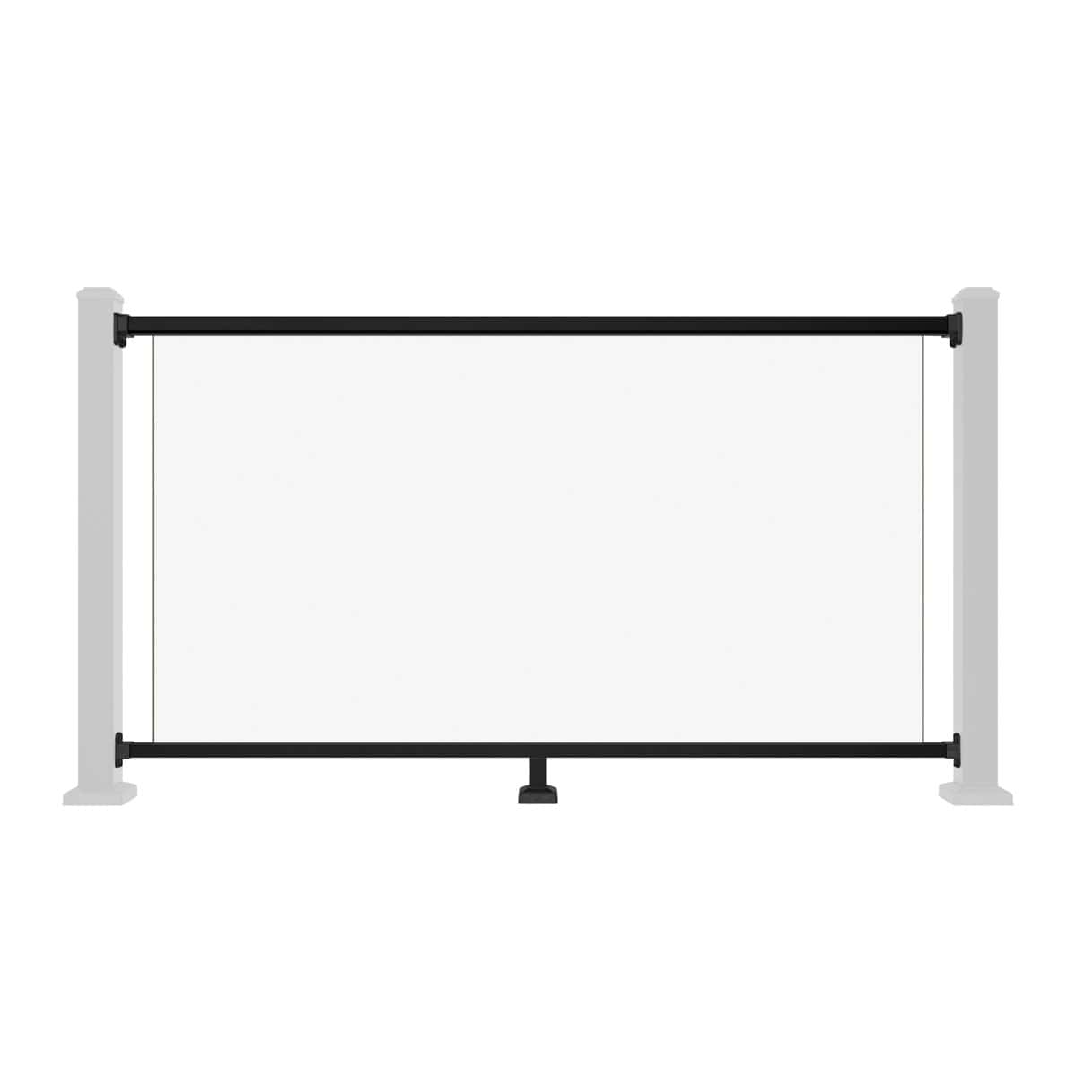
Learning how to install aluminium balustrade glass railings starts with the correct assembly sequence. Once the posts are securely fixed, plumb and square, the next stage is to prepare the rails, set their height, attach the brackets and seat the glass panel within the top and bottom channels.
This guide covers the NeoTimber® straight glass railing system in six steps. Fit the foot blocks before positioning the rail set, and arrange two people for Steps 5 and 6. Accurate measurements and careful handling help keep the panel aligned throughout the installation.
Before You Begin
Check that the posts and supporting structure have been installed for the intended application. Use this guide alongside the current NeoTimber® aluminium balustrade installation resources and the instructions supplied with your components.
- Confirm that the rail set, glass panel, brackets, foot blocks and supplied fixings are present and undamaged.
- Have a tape measure, pencil, spirit level and suitable drill and driver ready. Follow the product instructions for drill sizes and fixing details.
- Keep the working area clear and use suitable protective equipment and glass-handling equipment.
- Check the glass for damage before lifting. Do not fit a chipped or cracked panel.
The dimensions below apply to the NeoTimber® assembly described here; they are not universal dimensions for every glass balustrade system.
Step 1: Attach the Foot Blocks to the Bottom Rail
Prepare the bottom rail before bringing the rail set between the posts. Mark the foot block connector fixing position on the underside of the rail, pre-drill the marked hole and secure the connector with the screws provided. Fit the foot blocks as directed in the supplied instructions.
Complete this stage first so the bottom rail has its required support when positioned.


Step 2: Slide the Brackets onto the Rails
Slide the top handrail bracket onto one end of the top rail and the bottom rail bracket onto the corresponding end of the bottom rail. Check their orientation against the installation diagram before proceeding.
Each bracket should sit correctly on its rail. Resolve any alignment issue now, before marking or drilling the posts.

Step 3: Set the Rail Height Between the Posts
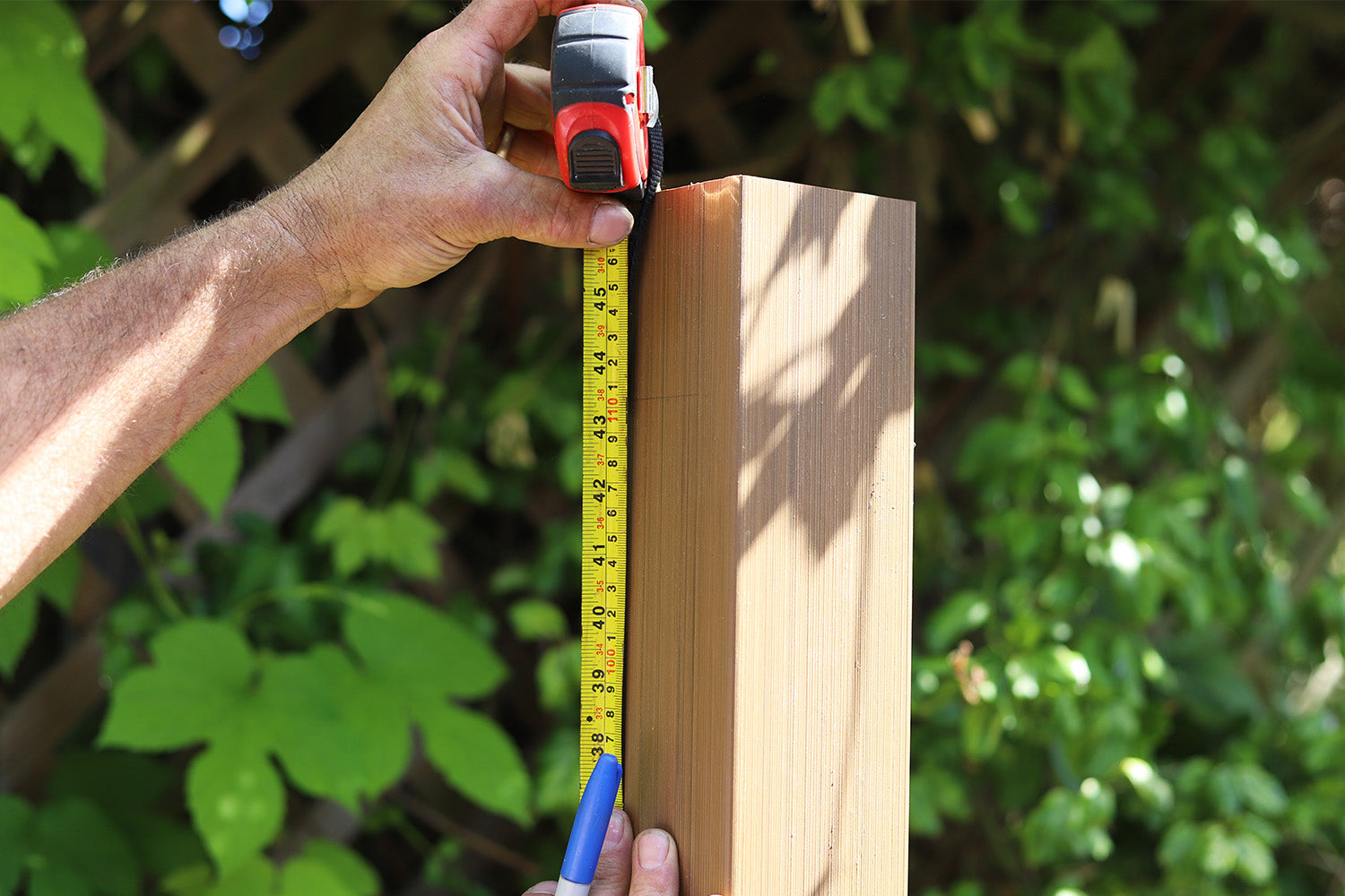
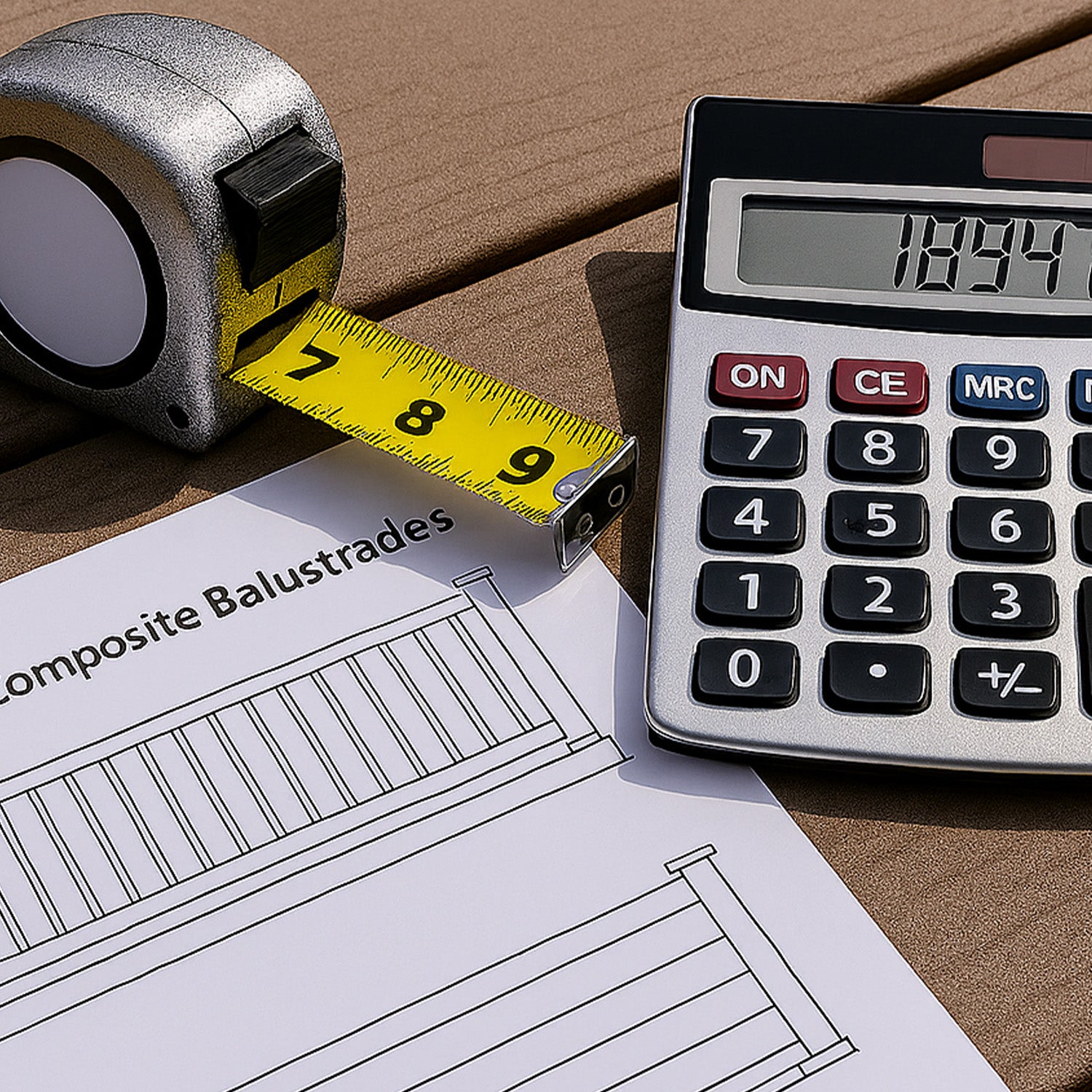
Offer the rail set into position between the fixed posts. Measure from the finished floor surface, using the following reference points:
- Bottom rail: the underside must sit 98mm above finished floor level.
- Top handrail: the top face must sit 1,105mm above finished floor level.
Confirm both measurements at each post and check the rails for level before marking the bracket positions. Adjust the position as needed rather than relying on measurements taken at only one end.

Step 4: Mark and Secure the Rail Brackets
With the rail set held at the correct height, centre each bracket on the post face and mark its screw holes with a pencil.
Drill the marked positions in accordance with the product instructions, then secure the brackets using the supplied self-tapping screws. Check that the rail set remains level and square before fully tightening the fixings.


Step 5: Lift and Seat the Glass Panel
Two people are required for this step. Carefully lift the glass panel and guide its top edge upward into the U-channel in the top handrail until fully engaged. Align the lower edge with the bottom rail, then lower the panel into the bottom U-channel groove.
Keep the panel controlled throughout the movement and check that it seats evenly within both channels.


Do not force the glass into place. If it catches or resists, stop and carefully remove it with assistance. Check for obstructions and alignment issues before trying again. Never use tools to drive the panel into a channel.
Step 6: Fit the Rear Reinforcement Screws
Keep two people involved while completing the final fixings. Once the glass is properly seated and the rails have been checked for level and alignment, install one additional reinforcement screw through each bracket into its corresponding top or bottom rail.
Fit these screws from the rear, non-visible side, following the specified fixing positions. They complete the bracket-to-rail connections and provide additional rigidity.


Final Aluminium Balustrade Glass Installation Checks
Before bringing the area into use, inspect the completed assembly:
- Post caps are fitted and secure.
- Base cover trims are fixed with structural adhesive as specified.
- The glass is evenly seated within both U-channels, with no tilt or unintended gaps.
- Bracket screws and rear reinforcement screws are fitted and tightened.
- The rail set is level, with no loose components or unexpected movement.
- The completed installation has been checked against the manufacturer's instructions and project requirements.
If the glass is loose, uneven or incorrectly seated, keep the area out of use until the issue is resolved. A basic movement check does not replace any required structural verification or inspection.
Common Installation Questions
When should the foot blocks be fitted?
Fit them to the bottom rail before positioning the rail set between the posts. This is the first stage of the assembly sequence.
How many people are needed to install the glass?
Two people are required for fitting the panel and completing the reinforcement screws in Steps 5 and 6. Plan the lift and keep the panel controlled throughout.
What should I do if the glass will not seat properly?
Stop rather than forcing it. With assistance, carefully remove the panel and check the channels and rail alignment. Contact NeoTimber® if the cause is unclear.
Does this method apply to every aluminium glass railing?
No. This guide describes the NeoTimber® straight glass railing system. Other products or configurations may require different dimensions, components and installation methods.
Need Help Completing Your Glass Railings?
For support with rail alignment, glass seating or component identification, contact NeoTimber® before continuing. You can also visit our aluminium balustrade installation resources for the wider installation sequence, including preparation and post fixing.