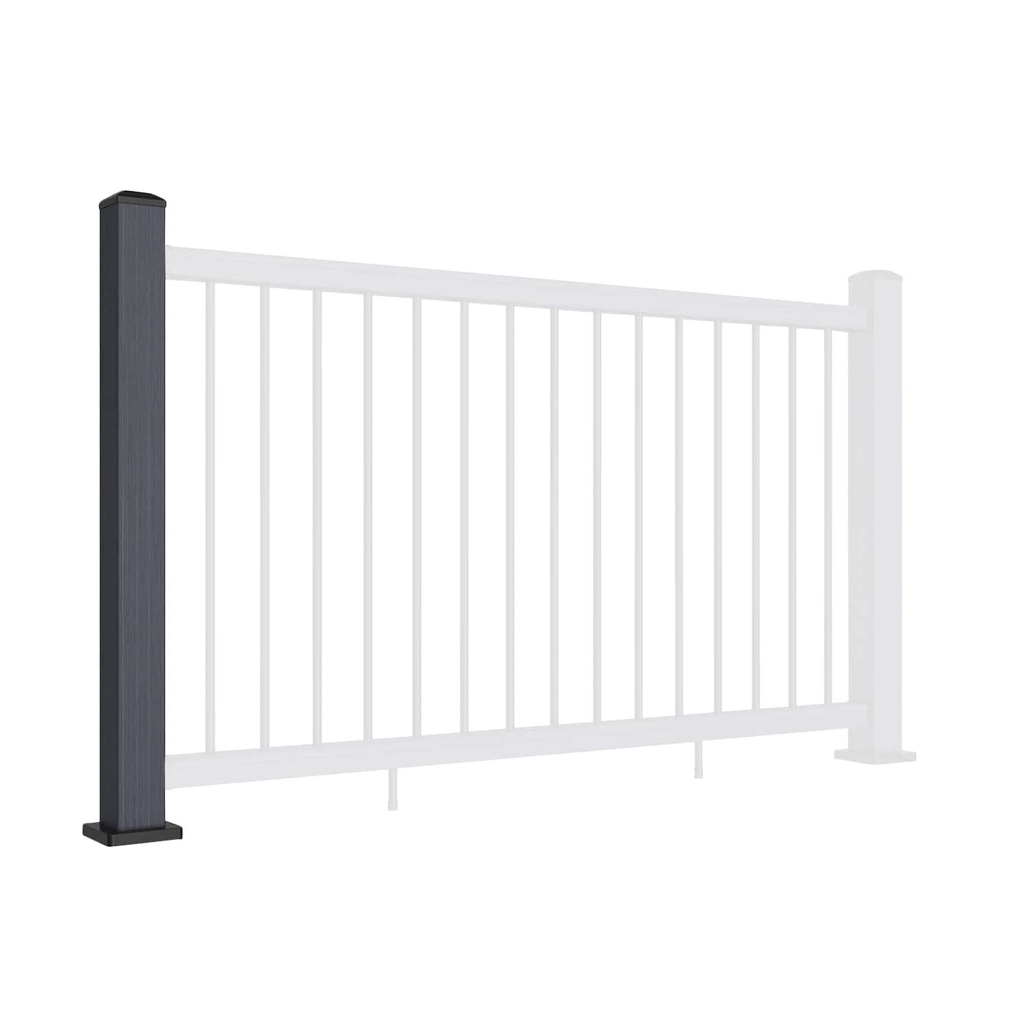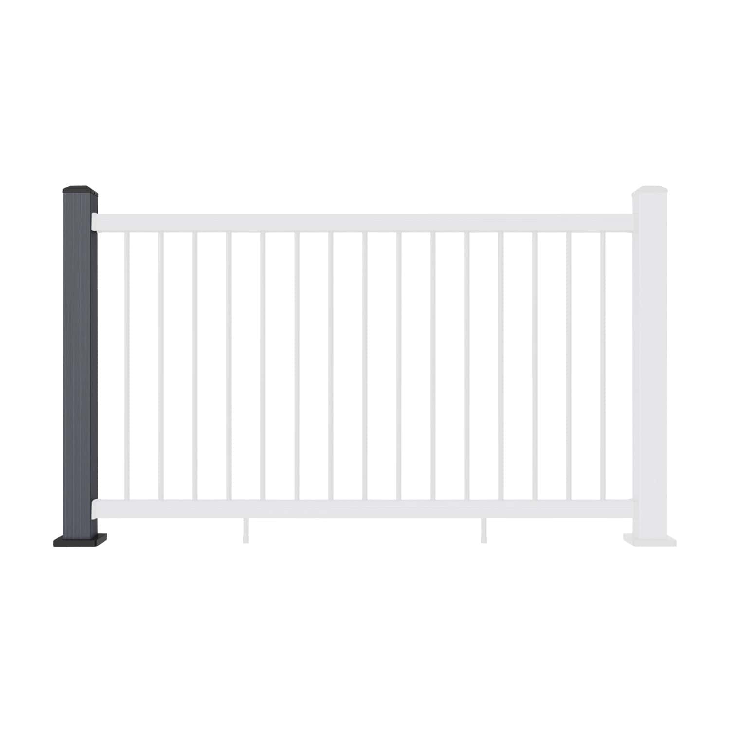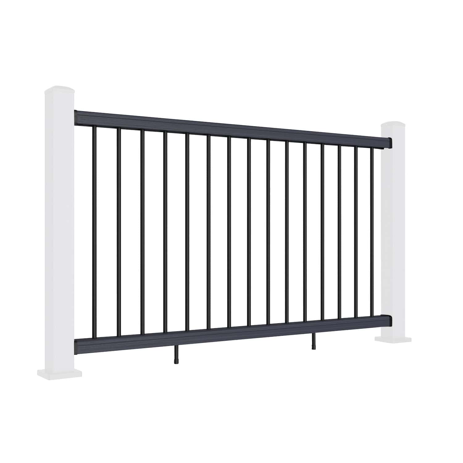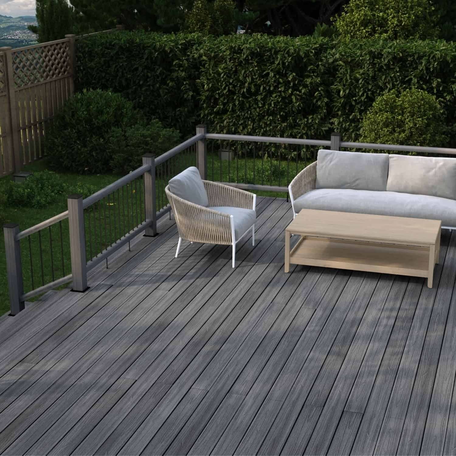





Aluminium Balustrade Wire Installation: Straight Runs, Corners and Stairs
This guide explains how to install aluminium balustrade wire railings using the NeoTimber® system. Follow the relevant sequence below to fit the handrails and support pickets, route the wire ropes and complete the tensioning and final fixings.
The support picket must be installed before threading the wires. At a 90° corner, complete and tension Bay 1 before starting the wire connections for Bay 2. Stair installations require setting out along the staircase slope rather than a horizontal measurement.
Before You Start
Confirm that all posts have been positioned, drilled and secured for the selected configuration. Refer to the aluminium balustrade post installation guide and current NeoTimber® installation resources before proceeding.
- Check handrails, brackets, support pickets, wires, tensioners and fixings against the supplied parts list.
- For corners, confirm the dedicated corner post and aluminium insert plate are available.
- For stairs, check that the adjustable bracket components suit the intended stair pitch.
- Prepare a tape measure, pencil, drill, suitable driver and the specified hex key or wrench.
- Confirm the required wire tension and fixing settings from the product instructions. Do not judge tension by appearance alone or tighten beyond the specified requirements.
The following sequence is specific to the NeoTimber® system. Confirm its suitability for the location and intended use, including the supporting structure and any guarding requirements, before installation.
Straight Aluminium Wire Railing Installation
Step 1: Position and Fix the Handrail
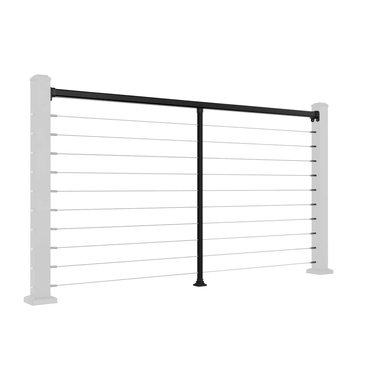
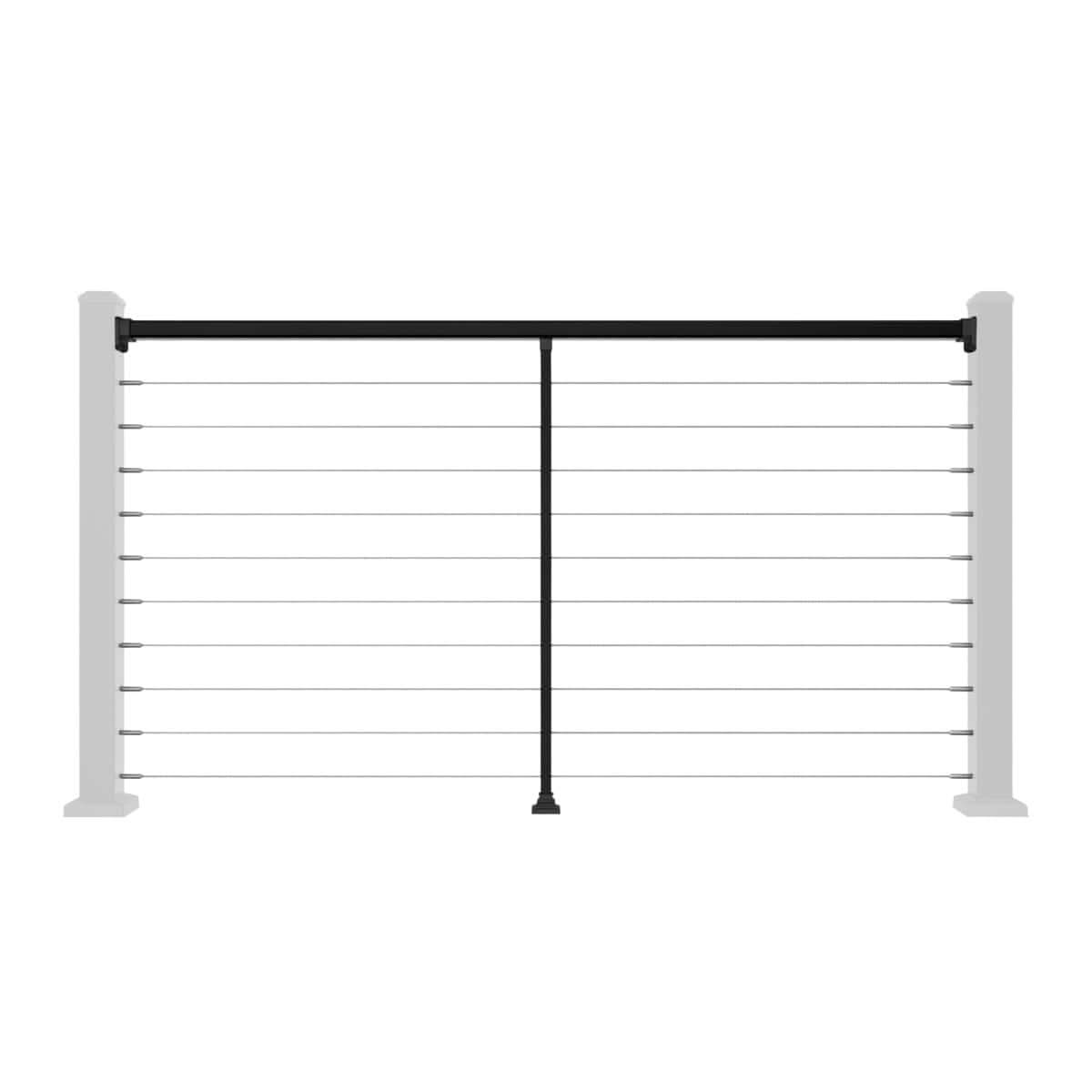
Slide brackets onto both ends of the handrail. Position the rail between the posts on the intended balustrade line, then mark the bracket fixing holes. Drill the pilot holes as specified and attach the brackets using the supplied screws.


For consecutive bays, leave the bracket fixings slightly loose during initial alignment, following the system instructions. Align the full run before completing the final tightening stage.

Step 2: Install the Central Support Picket
Position the support picket centrally beneath the handrail. Mark its base fixing holes on the deck, drill the required pilots and secure the base with the supplied fixings. Check alignment and fit the base cover.
This component supports wire alignment through the middle of the bay. Fit it before routing any wire ropes.


Step 3: Thread the Wire Ropes
Starting at an end post, insert the threaded bolts through the pre-drilled wire holes, working from the lowest wire upward. Attach a tensioner to each wire end and connect it securely to the corresponding threaded bolt as directed.

Feed each wire through the matching support picket hole and onward to the next post. Fit the tensioners and threaded bolt connections at the positions specified for the run, repeating until all wires are routed correctly.
Step 4: Tension the Wires and Complete the Fixings
Use the specified hex key to adjust the tensioners and secure their three locking nuts according to the supplied instructions. Work progressively across the wires, making small adjustments rather than fully tensioning one wire before moving to the next.
Maintain parallel alignment and use the manufacturer's tension requirements. If those settings are unavailable, confirm them with NeoTimber® before proceeding; do not substitute an estimated value.

Once all wires have the correct tension, recheck alignment and fully tighten the handrail bracket fixings as specified.

Check the Completed Straight Run
- Handrails are level and all bracket fixings are fully tightened.
- Support pickets are plumb and securely fixed.
- Wire ropes are parallel, correctly spaced and tensioned to specification.
- Locking nuts, post caps and base covers are secure.
Installing Wire Railings Around a 90° Corner
Two perpendicular bays connect at a dedicated corner post. Bay 1 uses the standard connections on the outer face; Bay 2 connects through an internal aluminium insert plate, fitted in Step 4 below.
Complete the Bay 1 wire tensioning before starting Bay 2. This sequence allows each set of connections to be installed and checked in turn.
Step 1: Fit the Handrail Brackets for Both Bays
Slide brackets onto the ends of both handrails and position the rails between their posts. Confirm a 90° angle at the corner, use the paper template to mark the fixing positions, then drill and attach the brackets with the supplied screws. Leave final tightening until the alignment and wire installation stages are complete.


Step 2: Fit a Support Picket in Each Bay
Position a picket centrally in each bay using the straight-run method. Mark and drill the base fixing holes, secure each picket, check alignment and fit the base covers.


Step 3: Thread and Tension Bay 1
Route the Bay 1 wires from its end post through the support picket to the corner post. Connect them to the threaded bolts on the outer face of the corner post. Adjust tension progressively and secure the locking nuts as specified before moving on.

Step 4: Install the Corner Post Insert Plate
Slide the aluminium insert plate into the corner post cavity. Align its pre-fixed nuts with the pre-drilled wire holes on the Bay 2 face, then secure the plate through the specified holes.

The plate provides the internal connections for Bay 2, allowing both sets of wires to align at the same heights without crossing inside the corner post.

Step 5: Thread and Tension Bay 2
Feed each Bay 2 wire from its end post through the support picket to the corner. Connect it to the insert plate using the threaded bolts on the Bay 2 face.
Apply the same progressive tensioning method used for Bay 1. When both bays meet the specified settings and remain correctly aligned, fully tighten the handrail brackets.


Check the Completed Corner
- The insert plate is secured and aligned with the Bay 2 holes.
- Wires in both bays are parallel, correctly tensioned and at matching heights.
- All locking nuts and handrail bracket fixings are secure.
- Post caps, base trims and picket covers are fitted.
Aluminium Balustrade Wire Installation on Stairs
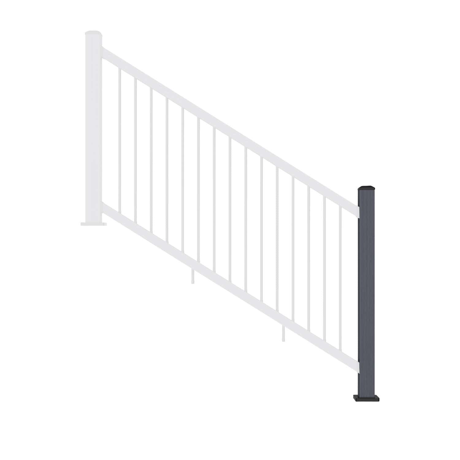
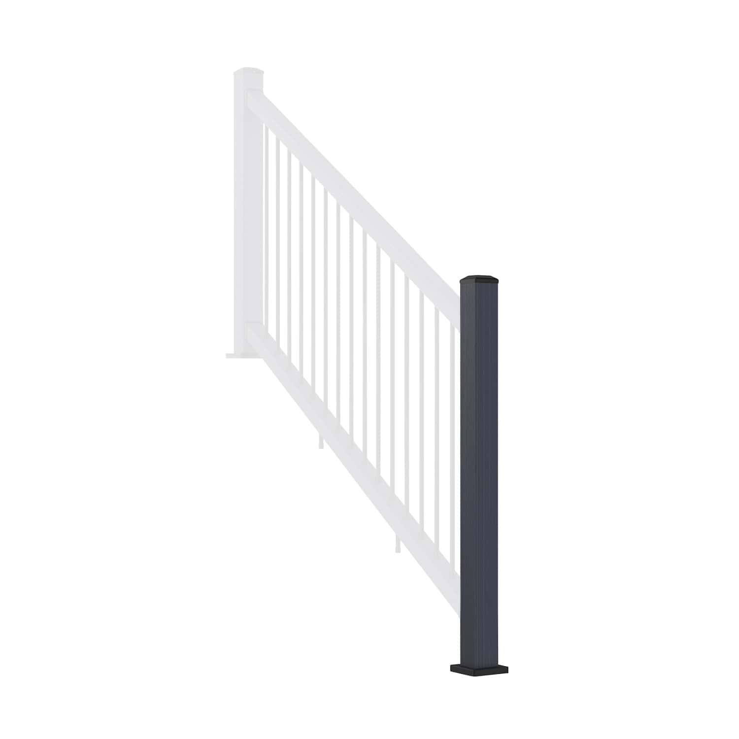
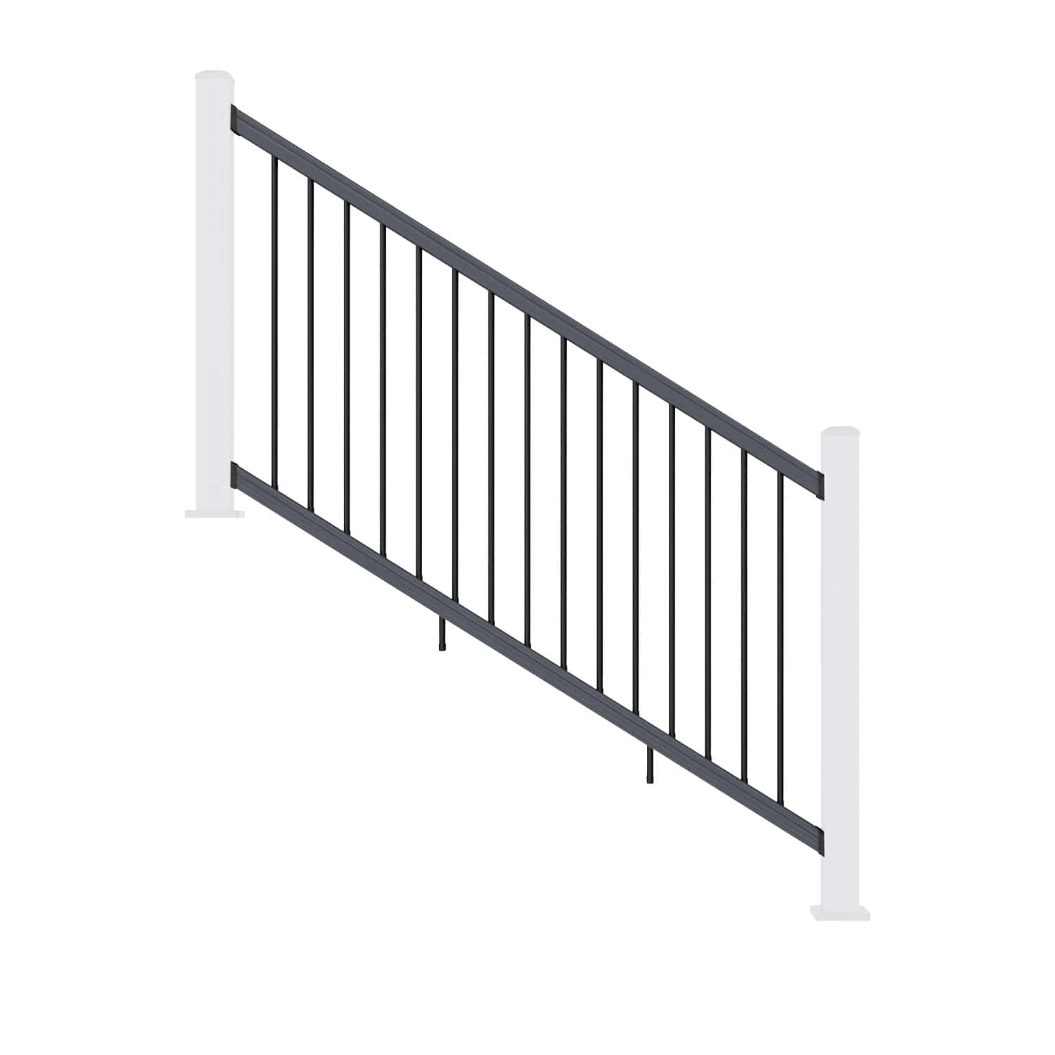
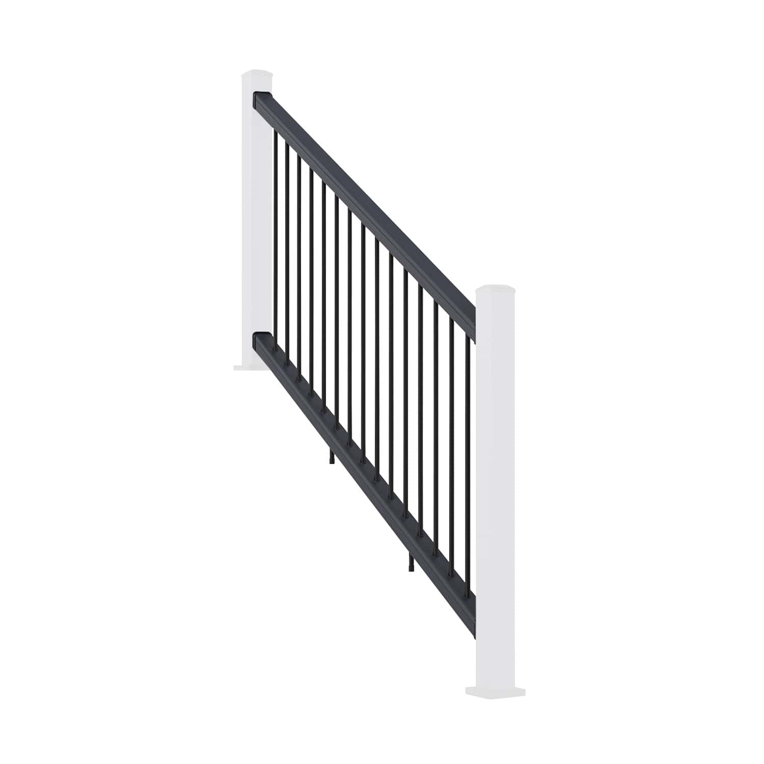
Stair wire railings use an angled handrail and adjustable bracket backing plates. The wire routing and progressive tensioning principles remain the same, but post holes, supports and rails must follow the stair configuration.
For the full section described here, the specified post-to-post distance is 1,910mm along the slope. Use the diagram's measurement points and supplied template; do not assume a horizontal or centre-to-centre measurement. Confirm hole alignment before permanently fixing the posts.
Step 1: Set Out and Fix the Stair Posts
Mark the post positions and check the sloping distance. Where fixed to decking, follow the illustrated minimum 50mm deck-edge setback, as well as the separate edge-distance requirements for the fixings and substrate.
Drill the specified pilot holes and secure posts with M8 timber screws for the timber arrangement or M8 expansion bolts for the concrete arrangement. Follow the actual fixing instructions for drilling, embedment and tightening. Check the posts are plumb, then fit their caps and base trims.


Step 2: Set the Handrail Angle and Backing Plates
Position the handrail between the posts to follow the stair pitch. Trim only where permitted by the product instructions, using suitable equipment for aluminium. Align the adjustable bracket backing plates beneath the handrail and centre them on the posts.

Mark the fixing holes, drill and secure the components with the specified screws. Use the paper template to check wire hole alignment against the stair angle before final tightening.

Step 3: Secure the Top Handrail Brackets
Slide the top brackets onto both handrail ends. Position the handrail on the installed post and bracket arrangement, checking the angle. Mark the remaining fixing positions, drill and secure with the appropriate screws.

Step 4: Fit the Stair Support Picket
Position the picket at the handrail midpoint. Mark and drill its base fixing holes on the supporting surface, then secure the base using the supplied fixings.

Mark and drill the picket bracket fixing positions beneath the handrail and attach the bracket. Check both the upper connection and the base before threading the wires.

Step 5: Route the Stair Wire Ropes
Thread the wires through the matching end-post and support-picket holes. Fit the supplied connectors and threaded bolts at the wire ends, following the straight-run connection method. Continue across the section and attach the opposite ends with the specified bolts and tensioners.

Step 6: Tension and Finish the Stair Run
Use the specified hex key or wrench to adjust the wires progressively and evenly. Check parallel alignment along the stair slope and confirm the required tension before securing all locking nuts.
Fully tighten the handrail bracket fixings and inspect the post and support connections. Investigate any unexpected movement or change in alignment before completing the work.


Check the Completed Stair Railing
- The handrail follows the intended stair angle.
- All handrail brackets and post fixings are secure.
- The support picket is fixed at its base and handrail connection.
- Wires run parallel along the slope and meet the specified tension requirements.
- Locking nuts, post caps and base trims are secure.
Keep the area out of use until the installation has been checked against the manufacturer's instructions and project requirements. A visual or basic movement check does not replace any required structural verification or inspection.
Wire Balustrade Installation FAQs
Why must the support picket be installed first?
It provides the intermediate routing points for the wires. Fitting it first lets you thread each wire through its matching holes before tensioning.
How much tension should the wires have?
Use the tension requirements for the supplied system. Adjust progressively across the wires rather than tightening one fully at a time. Ask NeoTimber® for the settings if they are not included with your instructions.
Which bay is installed first at a 90° corner?
Thread and tension Bay 1 first. Fit the internal corner post insert plate, then connect and tension Bay 2.
Is stair post spacing measured horizontally?
No. For the stair configuration described here, measure the specified 1,910mm along the slope at the reference points shown in the installation diagram.
Need Help with Your Wire Railing Installation?
Visit the NeoTimber® aluminium balustrade installation hub for related guidance. For help with tension settings, corner connections or component alignment, contact NeoTimber® before continuing.