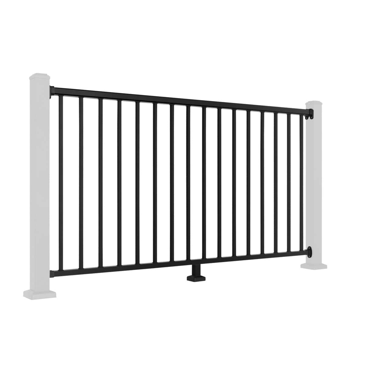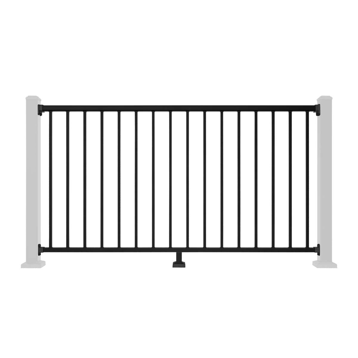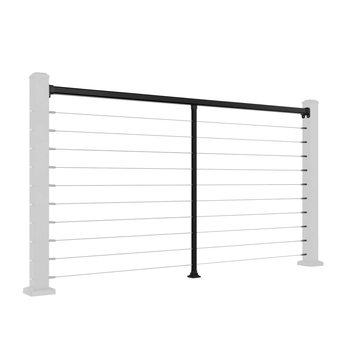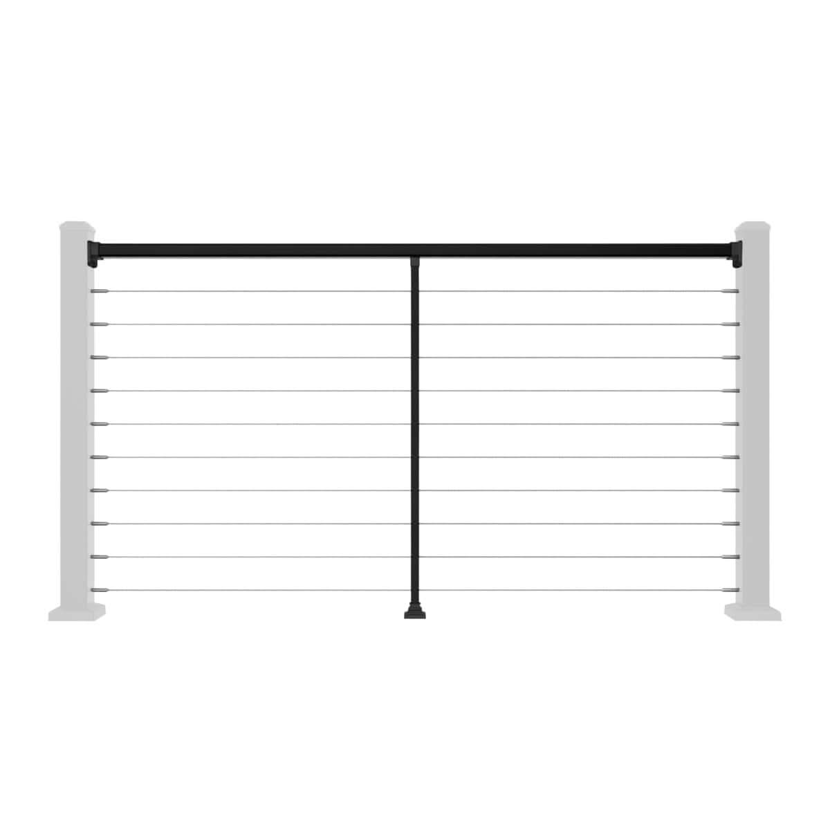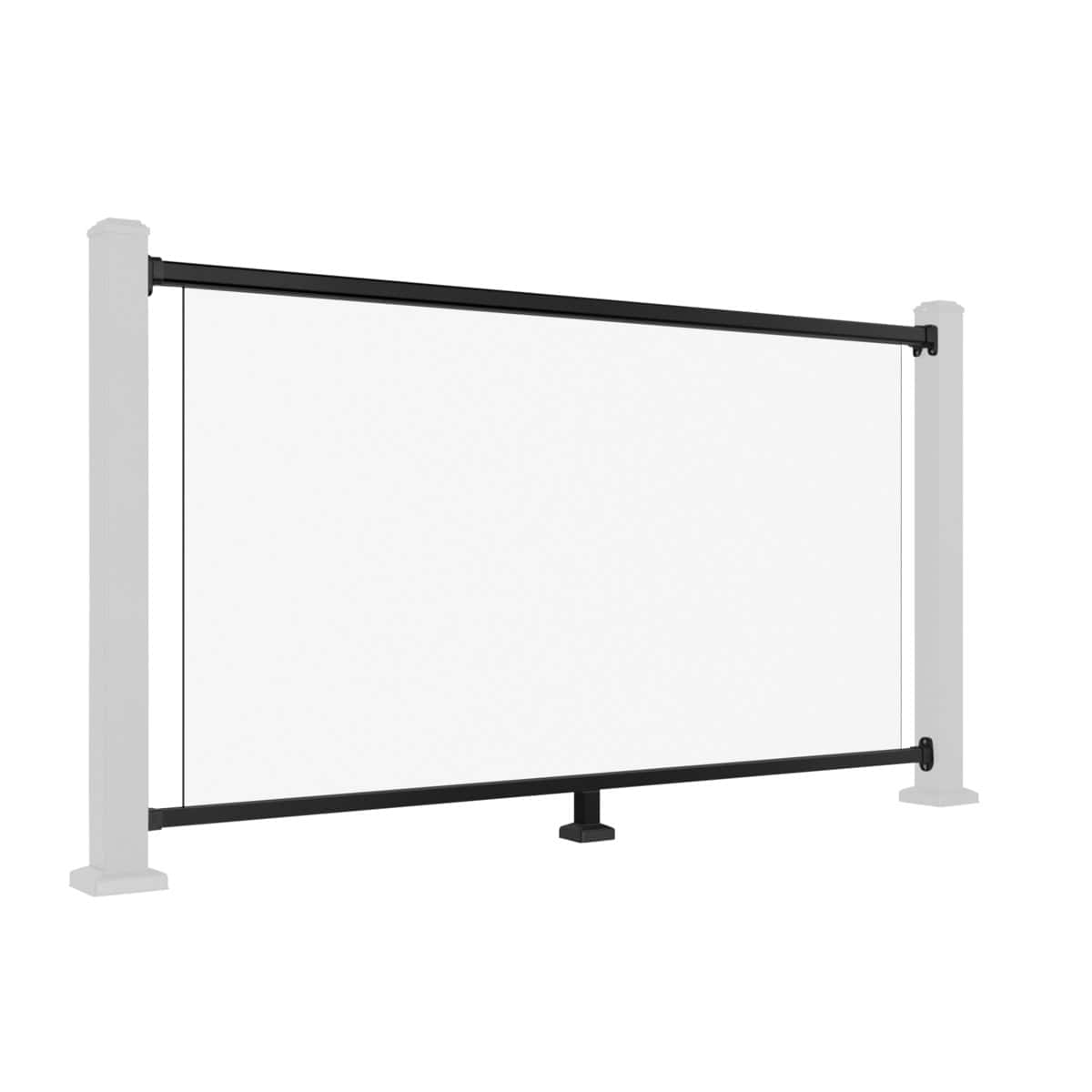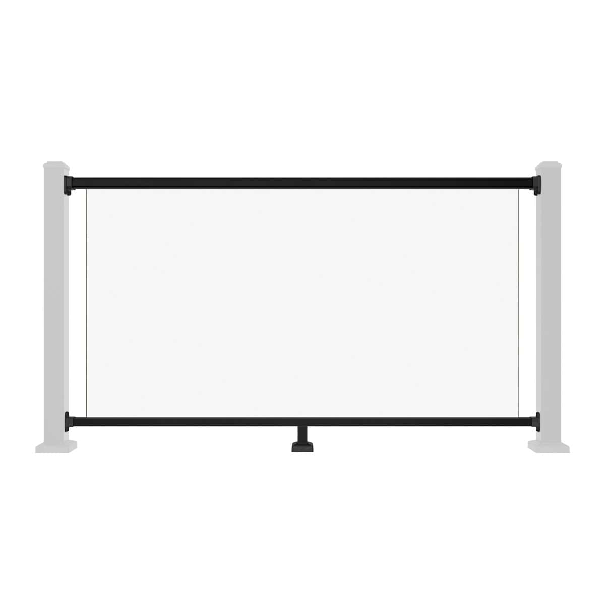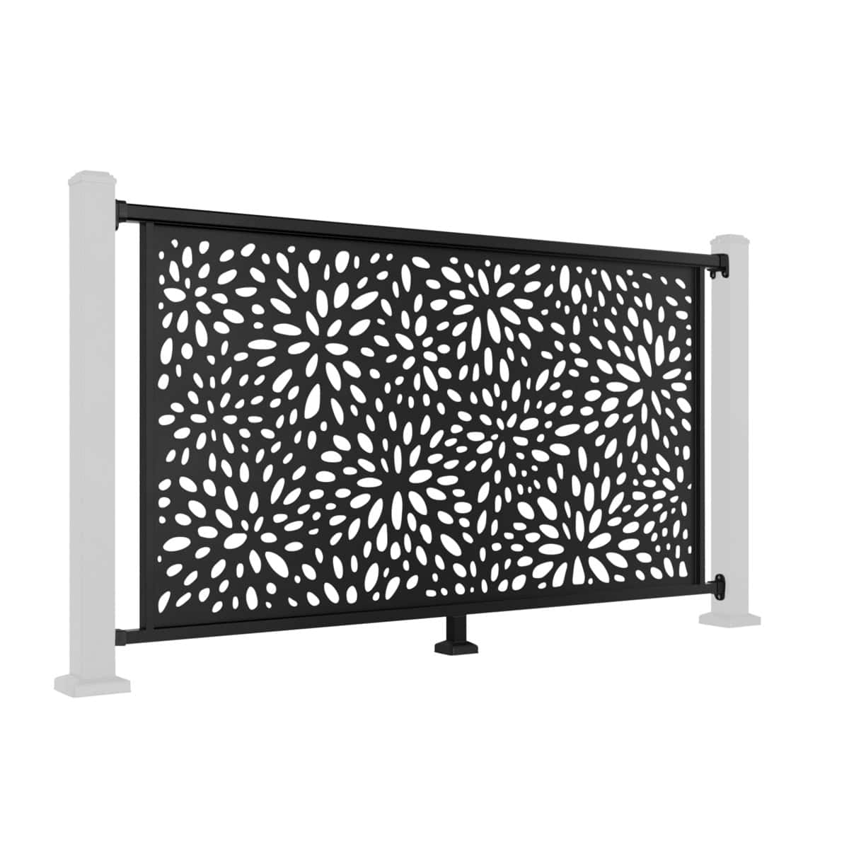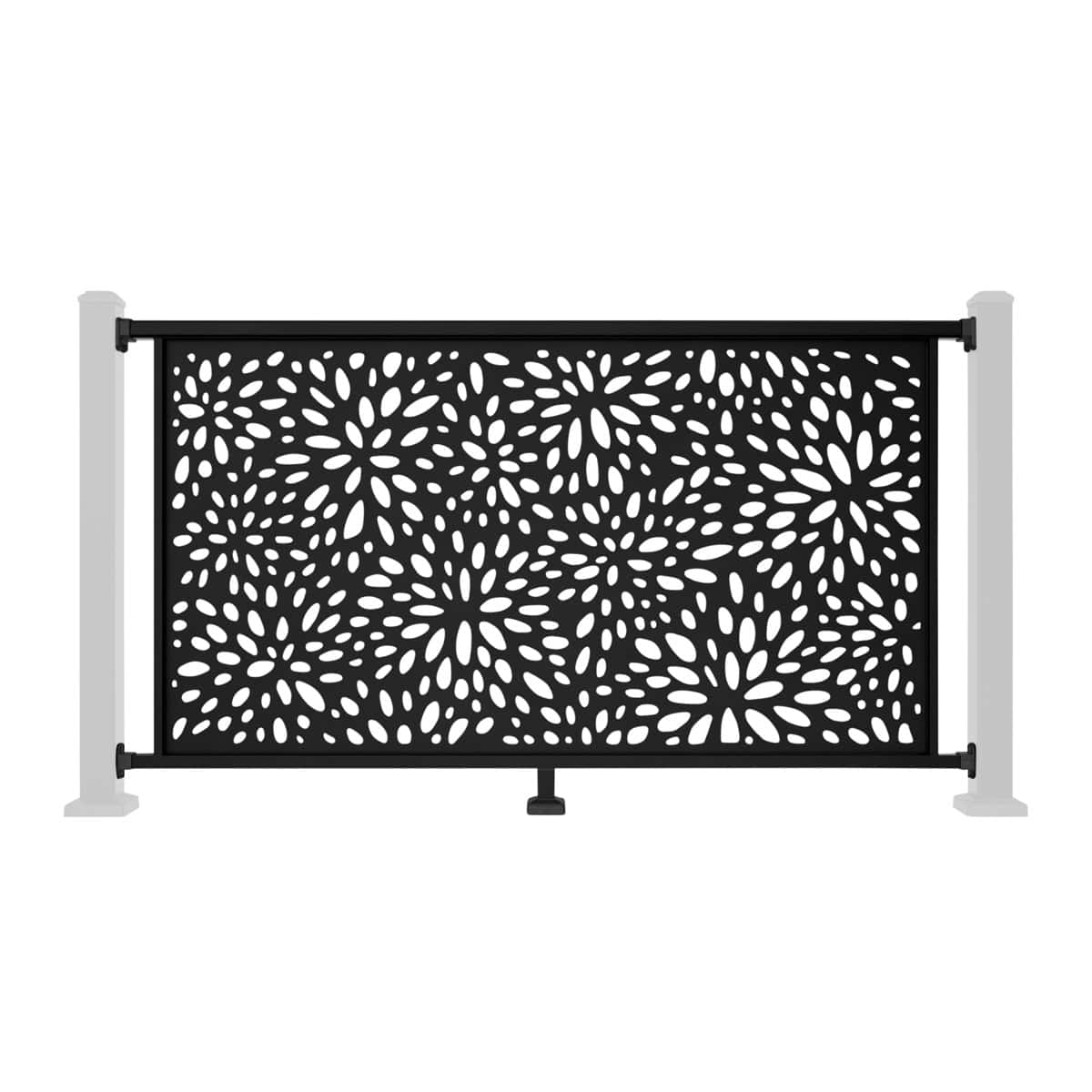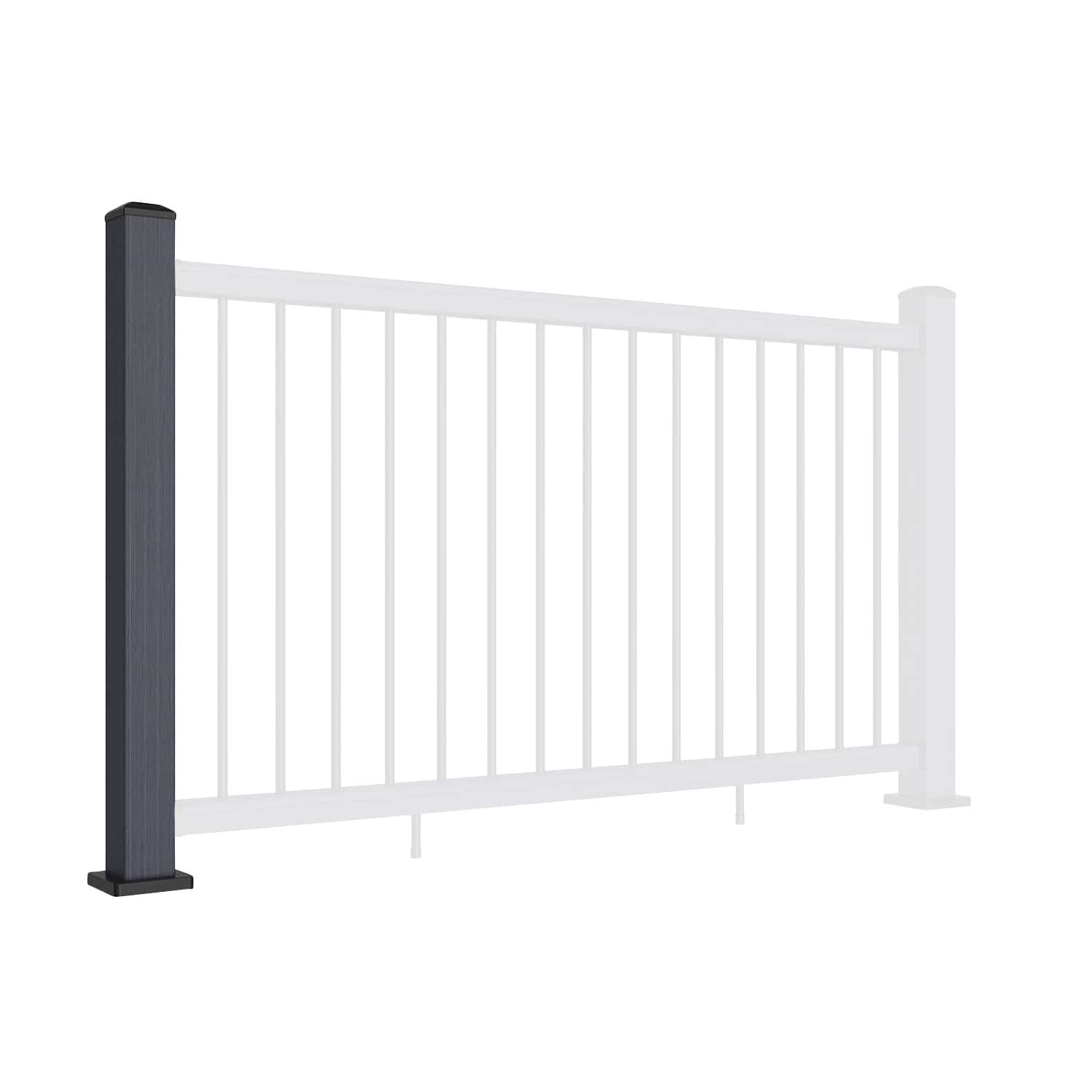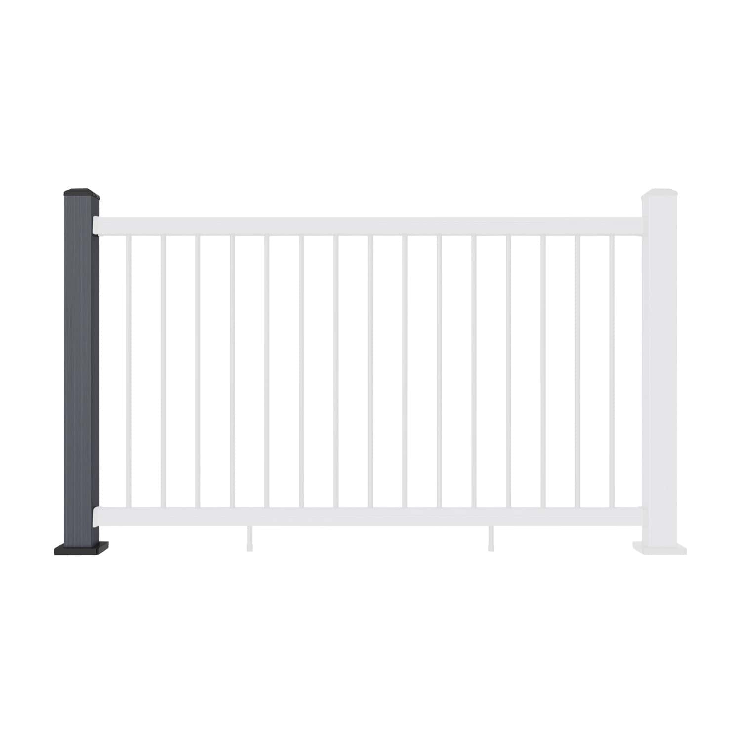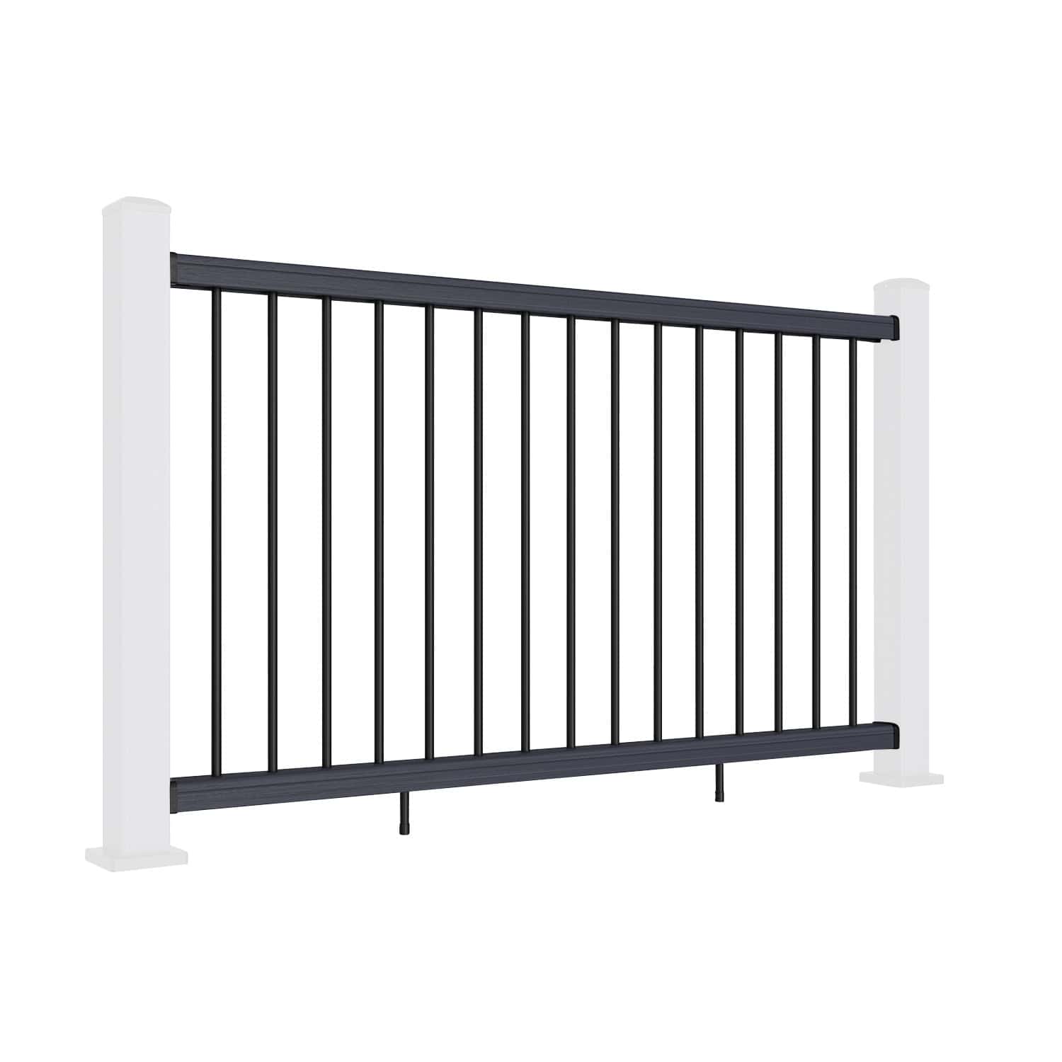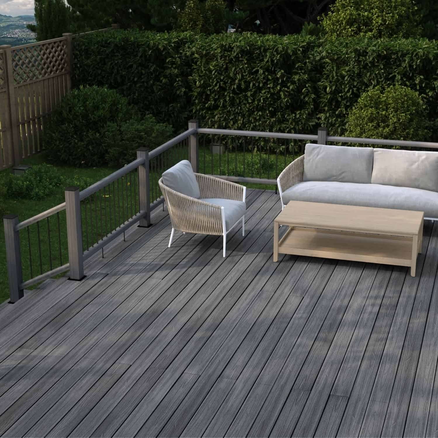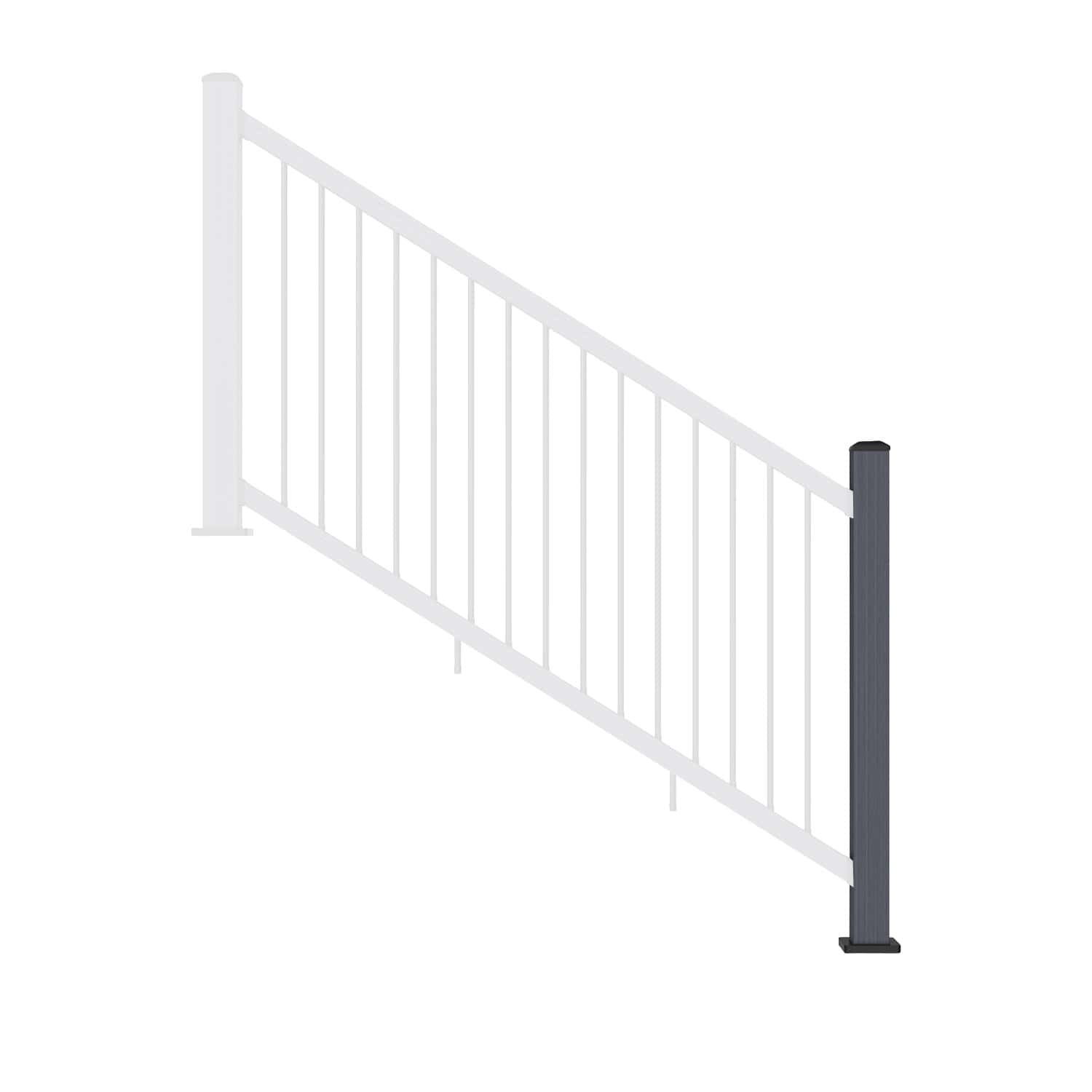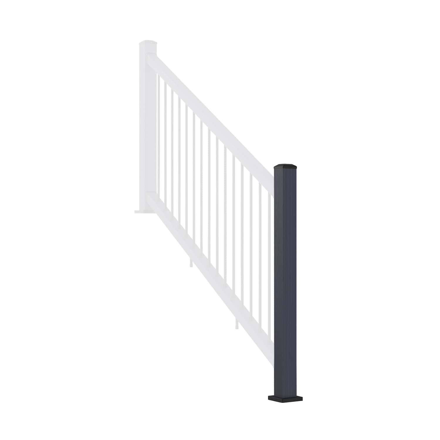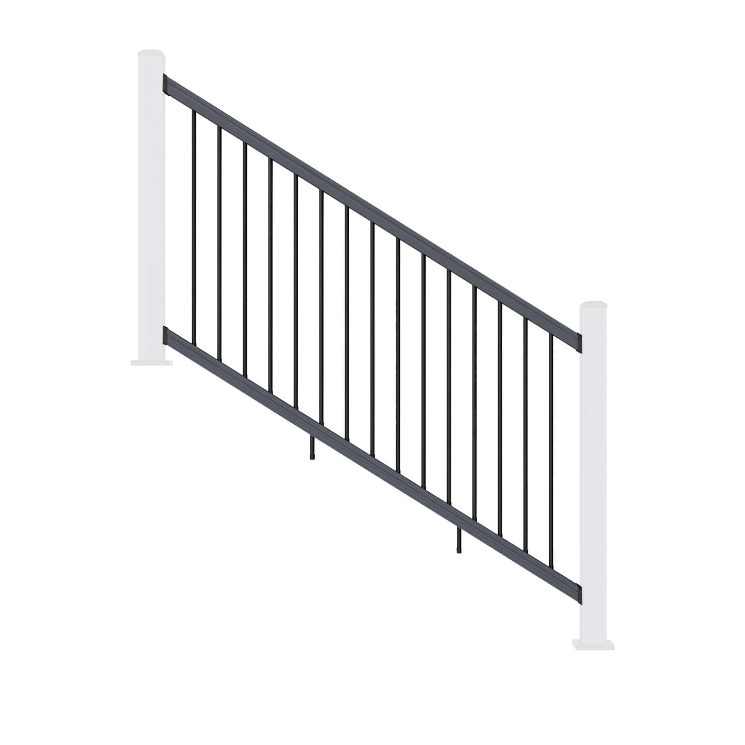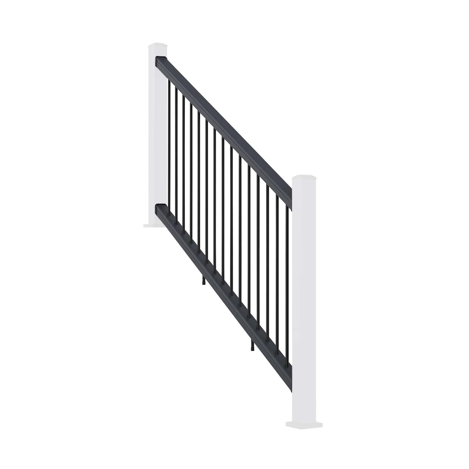

How to Fit NeoTimber® Straight Balustrade Rails on a Level Surface
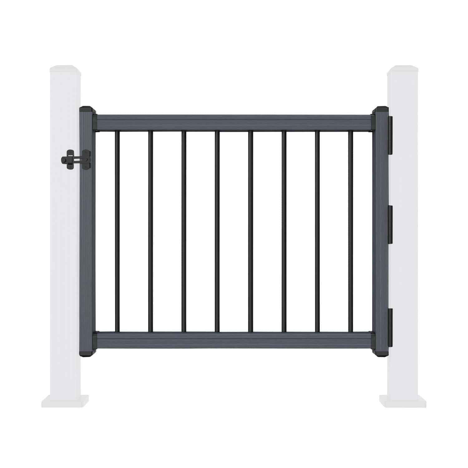
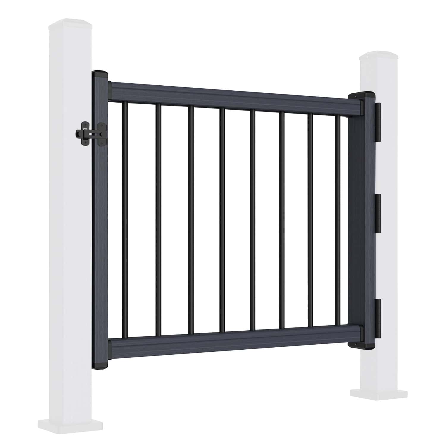
Installing composite balustrade straight railings starts with accurate post positioning and a suitable supporting base. This guide follows the NeoTimber® assembly sequence, from setting out the post mounts to fitting the rails, aluminium balusters and finishing pieces.
Use the steps and diagrams below to install composite balustrade straight railings on a straight, level run. Read them alongside the current composite balustrade installation instructions supplied for your product. Stair sections require their own configuration and fitting method.
Before You Begin
- Confirm the layout, finished height and suitability of the complete balustrade for the intended location.
- Check that post mounts can be fixed to a suitable supporting structure. Decking boards alone are not the structural fixing base.
- Use the fixing method specified for your substrate; do not assume a screw shown in a diagram suits every base.
- Identify the supplied components, straight-railing template and fixings before starting.
- Have measuring tools, a level, suitable drill and bits, screw-driving equipment and cutting tools appropriate to the composite rails and metal inserts available.
- Use appropriate protective equipment when drilling and cutting, and check for concealed services before drilling the base.
The measurements below relate to the system illustrated. Check them against the instructions for the components you receive before drilling or cutting.
Step 1: Set Out the Post Mounts
Mark the positions for post mounts J-LV-0215-36. For the illustrated system, the maximum spacing is 1,910mm centre to centre, as shown in diagram 1. Check the full layout before fixing the mounts.

Step 2: Secure the Mounts and Fit the Sleeves
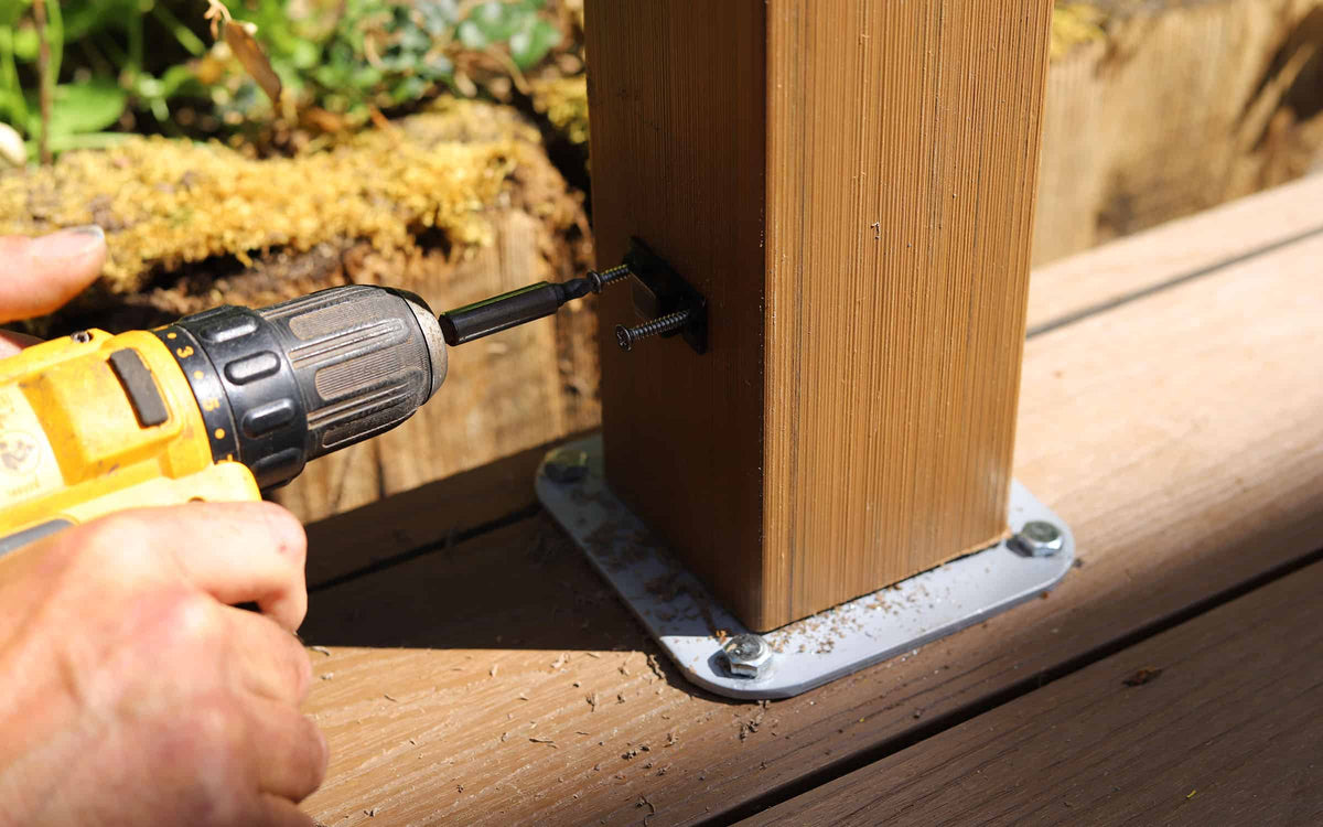
Install the post mounts using the fixing method appropriate to the supporting base. Diagram 2 identifies screw WJ0133 in the illustrated arrangement; confirm its applicability to your substrate. Slide post sleeve N-JM088 over each mount as shown in diagram 3.

Step 3: Mark and Pre-Drill the Bracket Positions
Use the supplied “Straight Railing” cardboard template to mark the post-bracket positions, following diagrams 4 and 5. Use the designated top-bracket marks and the bottom two holes for the lower brackets. Set the template from the ground-level reference to the top of its indicated line, as directed by the supplied instructions. Pre-drill the bracket holes with a 3mm bit.

Step 4: Fit the Post Skirts and Brackets
Lower post skirt K-LV-0199 over sleeve N-JM088, as shown in diagram 6. Secure the upper post brackets D-R0211 with screws WJ0130, following diagram 7. Secure the lower post brackets G-R0205 with screws WJ0131, following diagram 8.


Step 5: Measure and Cut the Rails if Required
The straight rails in this guide are supplied at a standard length of 1,810mm. If the opening requires a shorter rail, remove galvanised insert B-LV-0209 before cutting composite rail A-JM087.
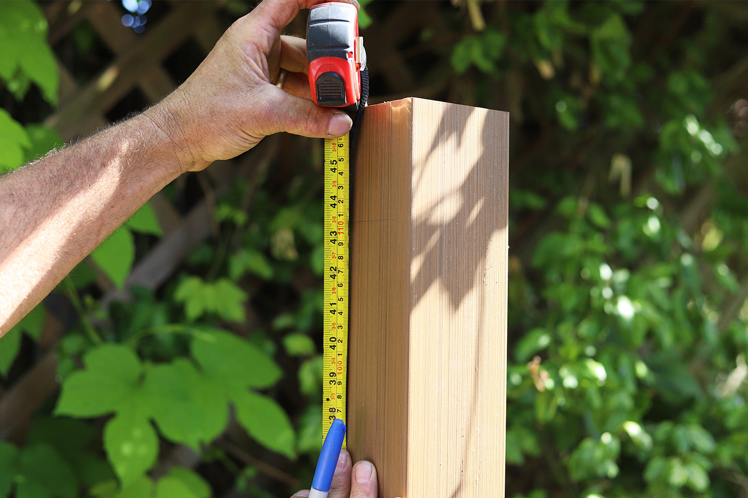
- Measure the clear distance between the post sleeves.
- Cut the composite rail to that distance minus 3mm at each end, allowing for gaskets FR0102, as shown in diagram 9.
- Cut the galvanised insert 6mm shorter than the cut composite rail.
- Retain at least 75mm between each rail end and its first baluster hole, following the measurement shown in diagram 10.
Check both ends before cutting. If the required opening cannot be achieved while retaining the specified end distances, resolve the layout with the supplier before proceeding.


Step 6: Attach the Bottom Rail Brackets
Fit bottom rail brackets H-R0204 using screws WJ0020. Follow the 29.5mm and 24mm locating dimensions shown in diagram 11; refer to the diagram for their precise orientation. The original method also allows a flat board against the rail end to help position the bracket correctly.

Step 7: Fit the Foot Blocks and Check Rail Orientation
Pre-drill and attach foot blocks I-LV-0216 to the bottom rail using screws WJ0020, as shown in diagram 12. Space them evenly for the finished rail length and do not position them beneath a pre-drilled baluster hole.
Check the rail orientation before assembly: the top rail holes face downwards and the bottom rail holes face upwards, as illustrated in diagram 13.


Step 8: Position the Bottom Rail
Attach bottom rail A-JM087 to lower post brackets G-R0205, following diagram 14. Check that the rail is seated in the intended position before adding the infill.

Step 9: Insert the Baluster Plugs and Aluminium Balusters
Install baluster plugs E-LV-0218-B and aluminium balusters M-LV-0218-A-36 in the pre-formed positions, as shown in diagram 15. Follow the illustrated arrangement without changing the spindle layout.

Step 10: Attach the Galvanised Adaptors
Fit galvanised adaptors C-LV-0210 to both ends of galvanised insert B-LV-0209, as shown in diagram 16.

Step 11: Slide the Insert into the Top Rail
Slide the assembled galvanised insert B-LV-0209 into top rail A-JM087, following diagram 17.

Step 12: Fit the Top Rail
Position top rail A-JM087 onto upper post brackets D-R0211, as shown in diagram 18. Check that the balusters engage correctly with the top rail as the assembly is brought together.

Step 13: Secure the Rail Assembly
Pre-drill and secure the assembly using screws WJ0142 at the positions shown in diagram 19. Follow the supplied instructions for the drilling and fastening details.

Step 14: Fit the Post Caps and Gaskets
Attach post caps L-LV-0120 and gaskets F-R0102 as illustrated in diagram 20. The source instructions also refer to the gaskets as FR0102 in the cutting step; check these references against the supplied component list.

Step 15: Adjust the Foot Blocks
If required, adjust foot blocks I-LV-0216 to the correct height, following diagram 21. Complete the final checks specified in the installation instructions before the balustrade is used.

Final Installation Checks
Check the post connections, rail fixings, baluster seating and foot-block adjustment against the supplied instructions. Confirm that the completed arrangement matches the project specification. Investigate any movement, missing fixing or damaged component before allowing the balustrade to be used.
Installing Composite Balustrade Straight Railings: FAQs
What is the maximum post spacing?
The illustrated system specifies a maximum of 1,910mm between post-mount centres. This is not the clear opening between the post sleeves. Confirm the dimensions for your supplied system before setting out.
How much allowance should I leave when cutting the rails?
For the illustrated system, deduct 3mm at each end from the clear distance between sleeves. Cut the galvanised insert 6mm shorter than the composite rail, and retain the specified minimum 75mm distance from each rail end to its first baluster hole.
Should the metal insert be removed before cutting?
Yes. The supplied sequence requires removal of the galvanised insert before cutting the composite rail. Cut each material using the appropriate equipment and refit the insert as directed.
Which way should the rail holes face?
The top rail holes face downwards, while the bottom rail holes face upwards, so the balusters fit between them.
Can I use this method on stairs?
This guide covers straight, level railing runs. Follow the separate stair installation instructions and use the components specified for that configuration.
Can the posts be anchored to decking boards alone?
No. Use the specified connection to a suitable supporting structure or approved base. Select the post-fixing method for the actual substrate.