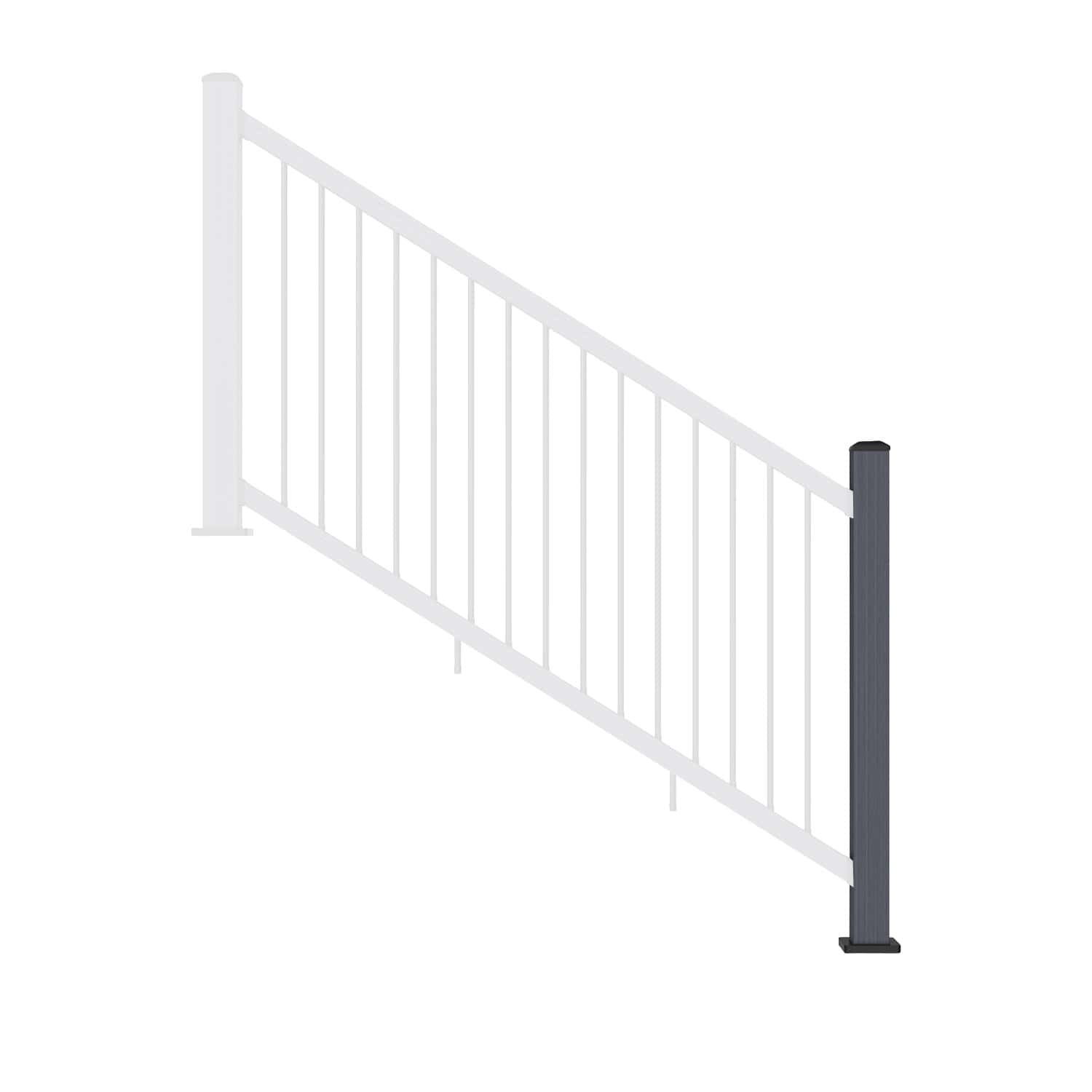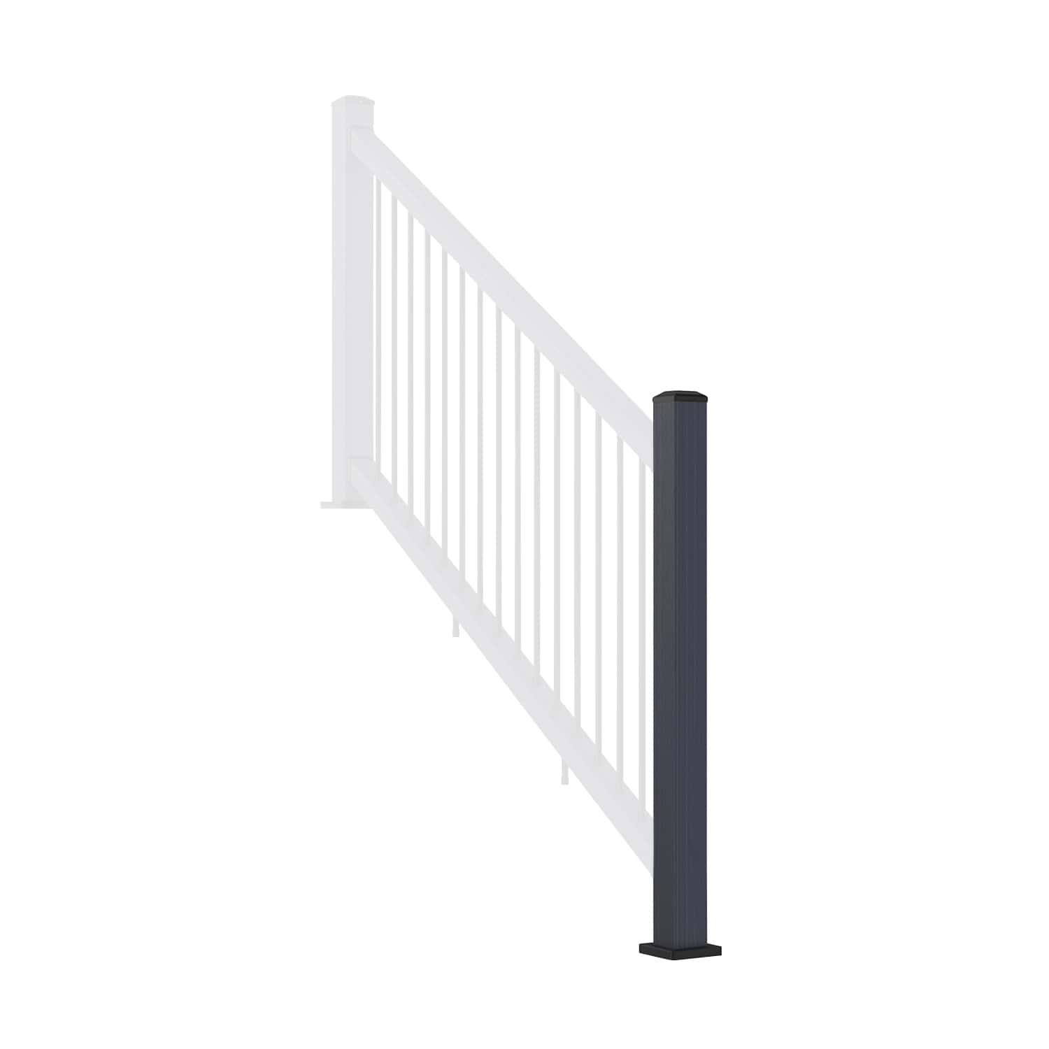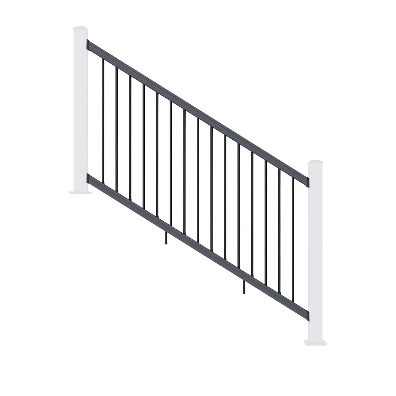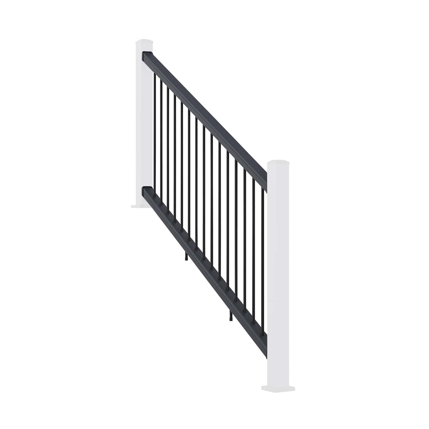

How to Fit NeoTimber® Composite Balustrades Along Stairs
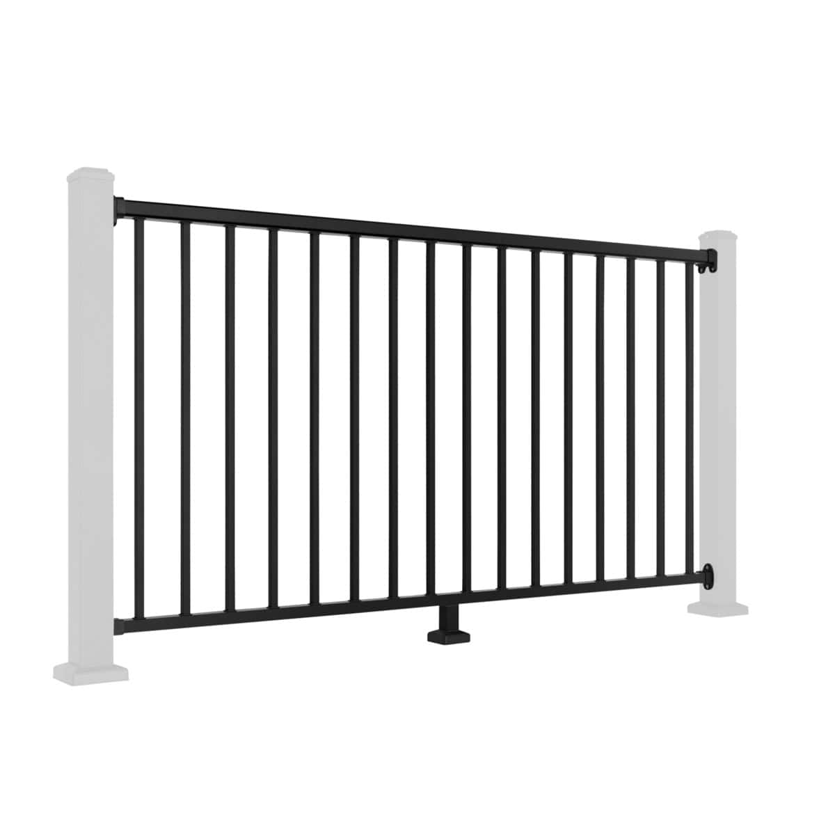
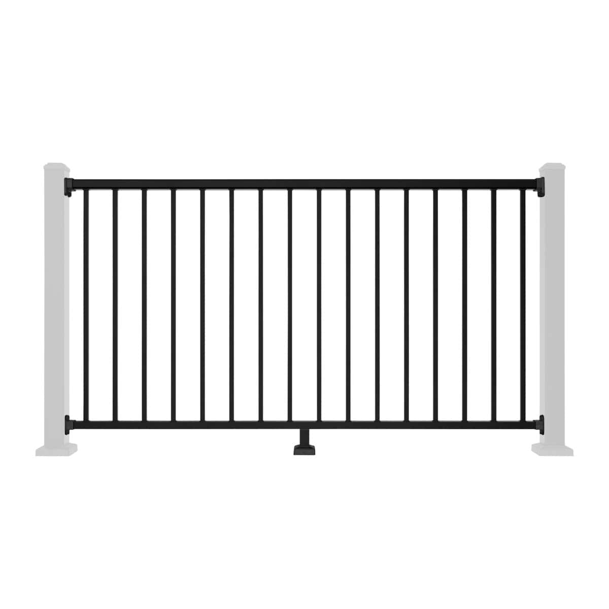
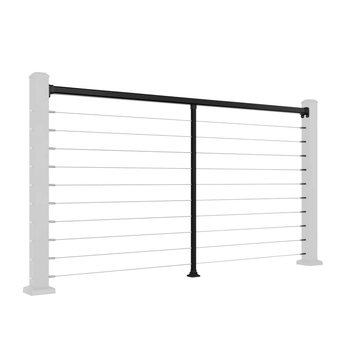
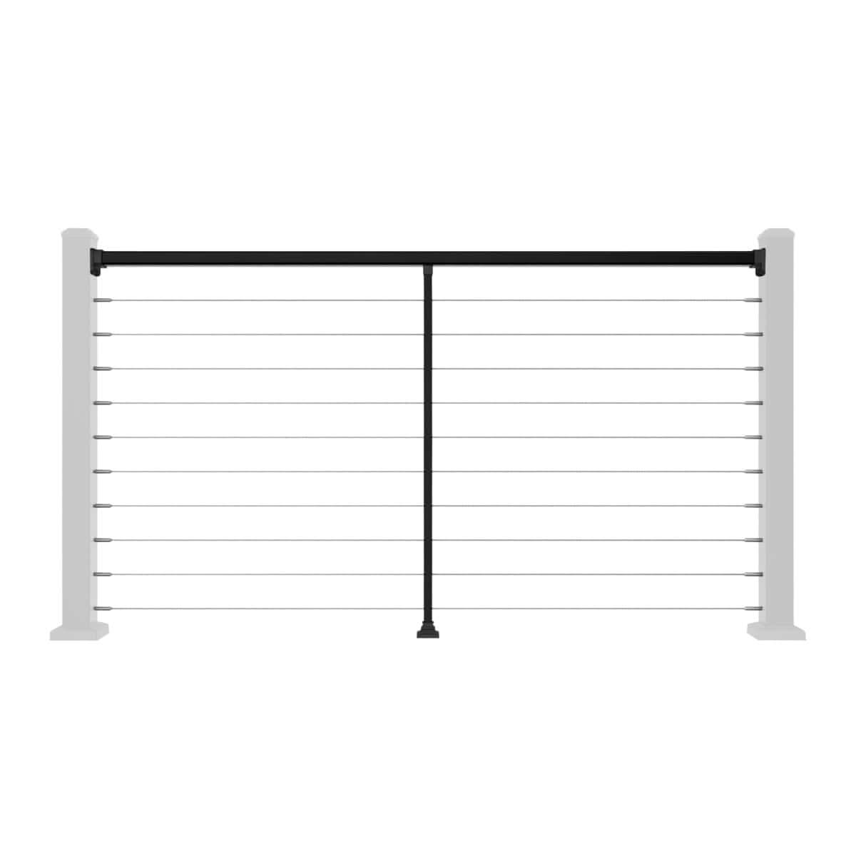
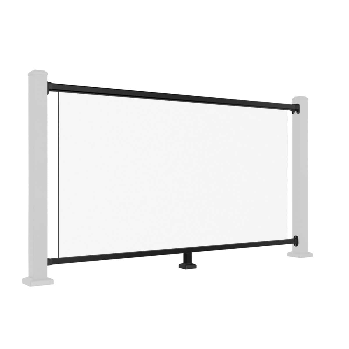
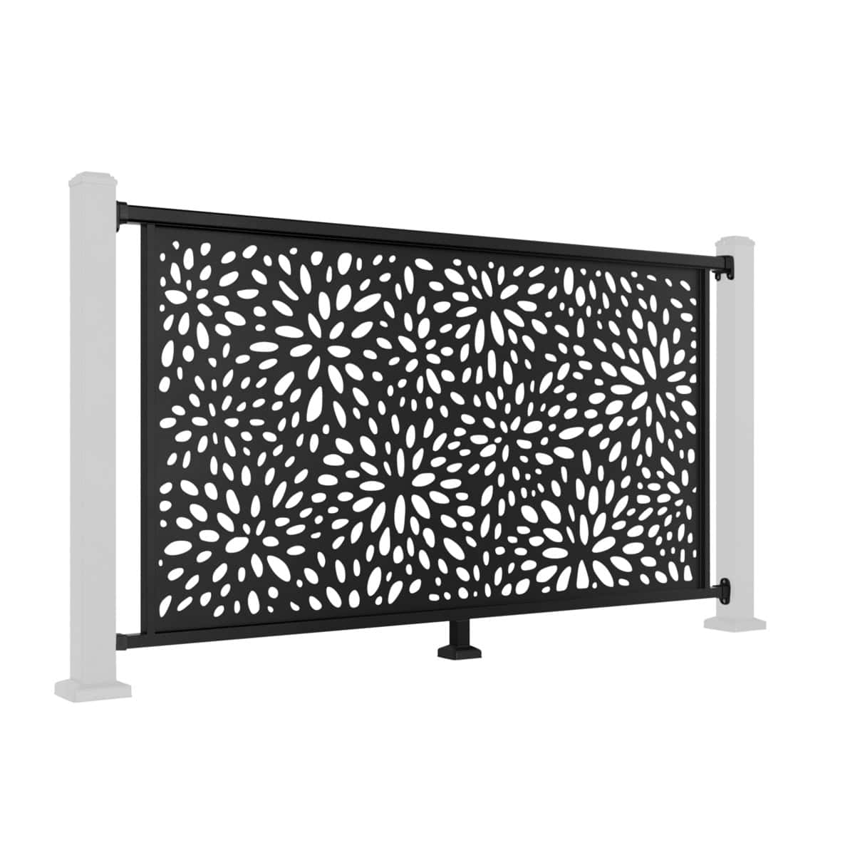
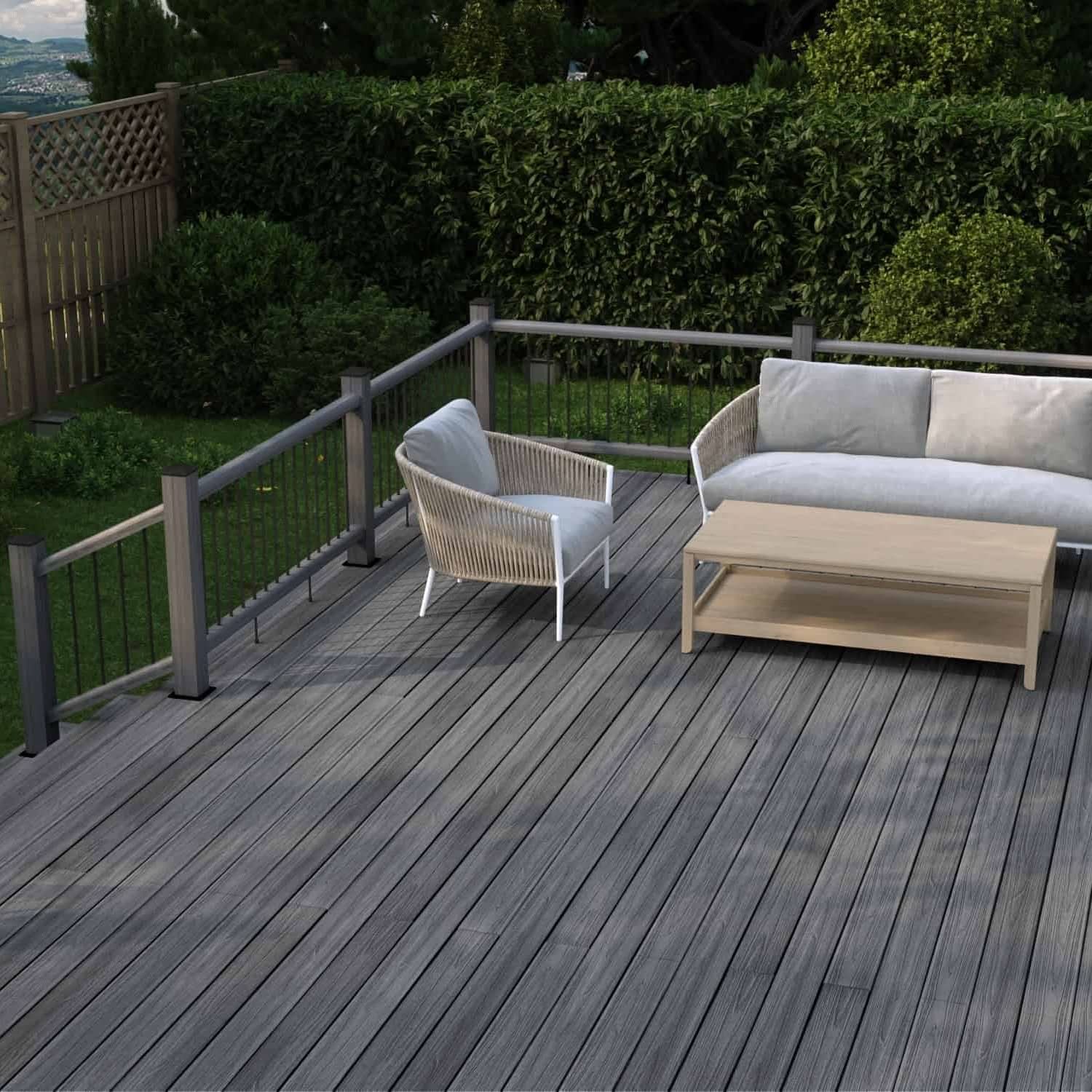
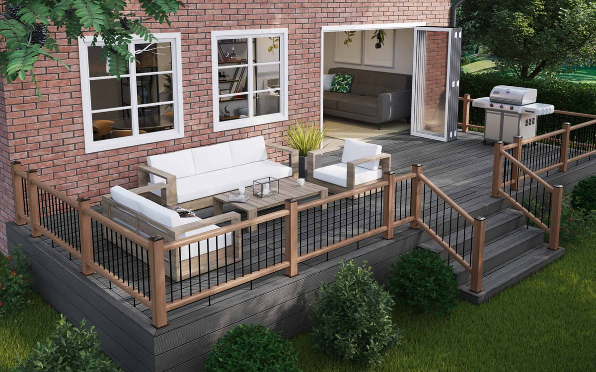
Installing composite balustrade stairs involves setting out the posts, preparing angled rails and fitting the balusters and finishing components. NeoTimber®’s hybrid balustrade system can be arranged to follow a flight of steps, creating a coordinated railing between different levels of your outdoor space.
This guide explains how to install composite balustrade stairs using the illustrated assembly sequence. Follow the 18 steps alongside the diagrams, and check the instructions supplied with your specific system before cutting or fixing components.
Before You Begin Your Stair Balustrade Installation
The illustrated arrangement uses a 32-degree railing angle. Its dimensions relate to this system and layout; confirm suitability before applying them to stairs with a different pitch.
- Check the post positions, supporting surface and required fixing method before starting.
- Identify the upper and lower ends of the stair run before marking or cutting.
- Match the components and fasteners to the supplied parts list.
- Read the complete fitting sequence, including the rail cutting allowances, before making any cuts.
Step 1: Mark the Post Mount Positions
Mark the positions for the post mounts (J-LV-0215-36). The maximum distance between mounts is 1646 mm for the arrangement shown in diagram 1. Use the diagram to identify the measurement points.

Step 2: Cut the Upper Post Mount and Sleeve
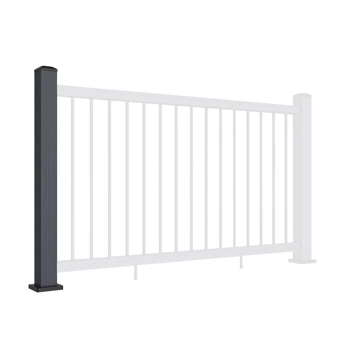
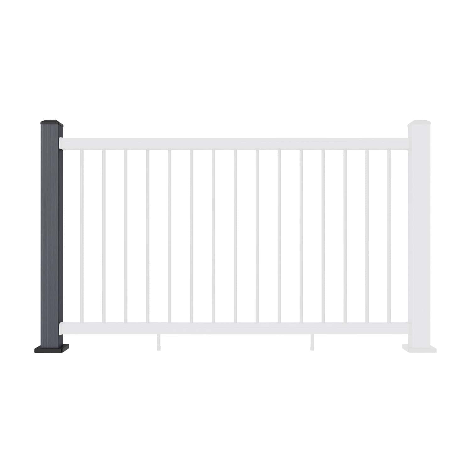
Cut the upper post mount (J-LV-0215-36) to 1130 mm, as shown in diagram 2, and the upper post sleeve (N-JM088) to 1160 mm, as shown in diagram 3. The lower post mount and lower post sleeve do not need to be cut for this arrangement.

Step 3: Secure the Post Mounts and Fit the Sleeves
Install the post mounts and secure them with WJ0133 screws, following diagram 4 and the fixing instructions appropriate to the supporting surface. Fit the post sleeves (N-JM088) as shown in diagram 5.

Step 4: Mark the Stair Bracket Positions
Use the “stairs – top post” cardboard template to mark the upper post. Use the four upper holes for the top brackets and the two lower holes for the bottom brackets. Measure the template position from the bottom as shown in diagram 6. Run string lines from the upper and lower template marks at the illustrated 32-degree angle to establish the railing alignment. Mark the drilling positions, then remove the template before pre-drilling.

Step 5: Pre-drill the Bracket Holes and Fit the Skirts
Pre-drill the post bracket holes as shown in diagram 7, using the bit size confirmed for the supplied fixings. The source instructions list both 3 mm and 5/32 inch, which are not equivalent; confirm the required size with NeoTimber® before drilling. Lower each post skirt (K-LV-0119) over its sleeve (N-JM088), following diagram 8.

Step 6: Fix the Post Brackets
Secure the top post brackets (D-R0203) with WJ0130 screws, as shown in diagram 9. Fix the bottom post brackets (G-R0205) with WJ0131 screws, following diagram 10.

Step 7: Measure and Cut the Rails and Insert
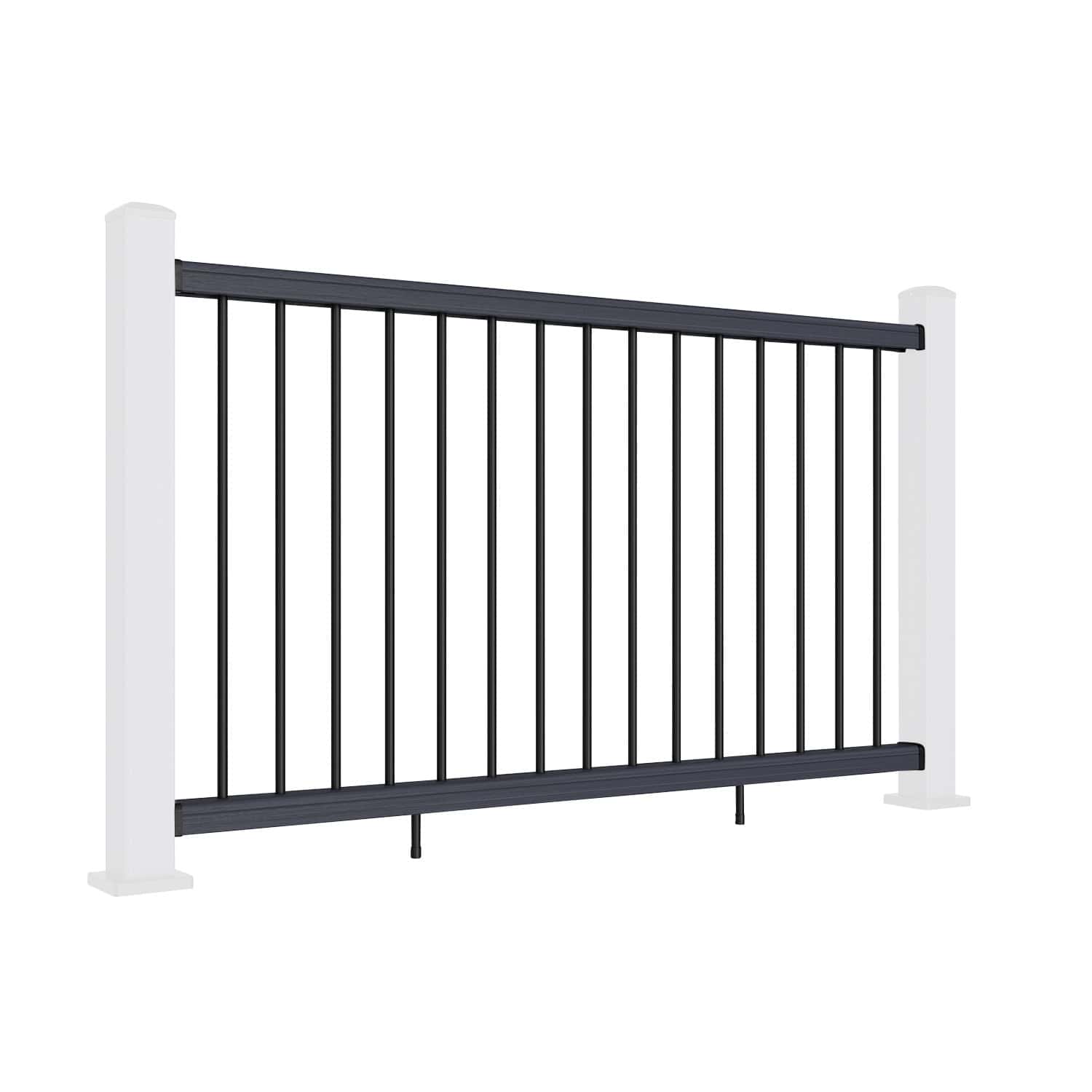
Measure and cut rails (A-JM087) to the length (L1 in diagram 11) between the post sleeve (N-JM088) minus 3 mm (0.118") on each side for inserting gaskets (F-R0102) at a 32-degree angle. Calculate L1 as the measured span L minus 3 mm at each end, following diagram 11. Remove the galvanised insert (B-LV-0209) before cutting rails. The galvanised insert (B-LV-0209) should be cut 6 mm shorter than the rail (A-JM087).

Leave at least 83 mm (3.3") between the ends of the rail and the first hole of each end as shown in diagram 12.

The galvanised insert (B-LV-0209) is designed for a maximum of 1825.7 mm (71.9") as shown in diagram 13. The railing is designed for a maximum of 1857.5 mm (73.1") as in diagram 14.

Step 8: Position the Bottom Rail Brackets
Fit the bottom bracket (H-R0204) with WJ0020 screws at 32.5 mm (1.28") and 24 mm (1") from the end of the rail which will be placed on the higher side of the stairs as shown in diagram 15. Fit the bottom bracket (H-R0204) with WJ0020 screws at 28 mm (1.1") and 24 mm (1") from the end of the rail which will be placed on the lower side of the stairs. Use a flat board to hold the bracket against the end of the rail to line up the correct distance.

Step 9: Fit the Foot Blocks and Orient the Rails
Pre-drill and fit the foot blocks (I-LV-0217) to the bottom rail using WJ0020 screws, as shown in diagram 16. Space the blocks evenly according to the finished rail length, avoiding positions directly beneath pre-drilled baluster holes. Orient the rails as shown in diagram 17: the top rail holes face downwards and the bottom rail holes face upwards.


Step 10: Attach the Galvanised Adaptors
Fit the galvanised adaptors (C-LV-0210) to both ends of the galvanised insert (B-LV-0209), following diagram 18.

Step 11: Insert the Reinforcement into the Top Rail
Slide the galvanised insert (B-LV-0209) into the top rail (A-JM087) as shown in diagram 19.

Step 12: Cut the Aluminium Balusters
Cut the aluminium balusters (M-LV-0218-A-36) to 896 mm for the illustrated installation, as shown in diagram 20.

Step 13: Fit the Bottom Rail
Attach the bottom rail (A-JM087) to the bottom post brackets (G-R0205), following diagram 21.

Step 14: Install the Baluster Plugs and Balusters
Fit the baluster plugs (E-LV-0218-C) and aluminium balusters (M-LV-0218-A-36) in the arrangement shown in diagram 22.

Step 15: Fit the Top Rail
Attach the top rail (A-JM087) to the top brackets (D-R0203) as shown in diagram 23.

Step 16: Secure the Top Rail
Pre-drill and secure the top rail with WJ0143 screws as shown in diagram 24. WJ0143 does not need to be completely fixed through the galvanised adaptors (C-LV-0210).

Step 17: Fit the Post Caps and Gaskets
Fit the post cap (L-LV0120) using WJ2020 and the gaskets (F-R0113 and O-R0115), following the assembly shown in diagram 25.

Step 18: Adjust the Foot Blocks
Adjust the foot blocks (I-LV-0217) to the required height where necessary, following diagram 26.

Frequently Asked Questions
How do I install composite balustrade stairs?
Start by positioning the post mounts, then prepare the posts, brackets and angled rails. Fit the reinforcing insert, bottom rail, balusters and top rail before completing the caps and foot blocks. Follow the full sequence above with the diagrams for the individual measurements and fixings.
Can I use these dimensions for any staircase?
No. This guide shows a specific NeoTimber® assembly with a 32-degree railing angle. Confirm the correct installation detail for your staircase and product before using the cutting dimensions.
Do both stair posts need to be cut?
For the illustrated arrangement, the upper post mount is cut to 1130 mm and its sleeve to 1160 mm. The lower mount and sleeve remain uncut, as explained in step 2.
Should I remove the metal insert before cutting the rail?
Yes. Remove the galvanised insert before cutting the composite rail. Step 7 specifies a separate cut for the insert and explains the gasket allowances and minimum distance to the first baluster hole.
Where should the foot blocks be fitted?
Fit the foot blocks beneath the bottom rail, spaced evenly for the finished rail length. Do not position them directly beneath pre-drilled baluster holes. Adjust their height at the final stage as shown in diagram 26.
Complete Your Stair Railing Installation
Working through the stages in order helps keep installing composite balustrade stairs manageable. Check the completed assembly against the supplied instructions, including bracket fixings, rail connections and foot block positions, before bringing the stairs into use.