



Prepare a Secure, Ventilated Framework for Your Cladding
Composite cladding subframe installation sets the foundation for the finished wall. The framework supports the boards, establishes their alignment and creates space behind the cladding for drainage and airflow. Planning it carefully also makes it easier to position board joints, finish corners and work around windows and doors.
This guide explains the main layout decisions and the process for fixing NeoTimber® composite joists to a suitable supporting wall. Read it alongside the NeoTimber® cladding installation resources and the instructions for your chosen products. The wall construction, exposure and project specification must inform the final fixing design.

What Does a Cladding Subframe Do?
The subframe provides the fixing points for the cladding boards and helps establish a consistent finished plane. It also separates the boards from the backing wall. That separation only works effectively when the layout preserves the intended ventilation and drainage routes.
A straight-looking frame is therefore only part of the job. Its anchorage, board support and junctions need equal attention. For a broader comparison of framework options, see our composite cladding frame and subframe guide.
Choose Suitable Joists, Battens and Wall Fixings
The NeoTimber® composite cladding joist measures 40 mm × 59 mm × 3,600 mm. Timber or aluminium battens may also be appropriate where the chosen system and project specification permit them.
Do not assume different materials share the same fixing method, movement allowance or structural capacity. The composite joist arrangement described here is a wall-supported cladding framework; it should not be treated as a freestanding structural frame or an unsupported spanning beam.
Wall anchors must suit the actual substrate. The screw or anchor type, length, embedment and spacing need to account for the supporting material, loads and any packing. A screw’s corrosion resistance alone does not establish that it will provide adequate anchorage.
Composite Cladding Subframe Spacing and Ventilation
The figures below summarise the guidance in the supplied NeoTimber® installation material. Confirm that they apply to your selected board, frame and project before setting out. More demanding conditions may require a specific design.
| Detail | Guidance | What to check |
|---|---|---|
| Batten centres | No wider than 500 mm | Measure centre to centre, not the clear gap between battens. |
| Higher wind exposure | The guide suggests reducing centres to 400 mm | This is not a substitute for checking the project’s wind loads and fixings. |
| Space behind boards | At least 35 mm | Maintain the intended cavity without obstructions. |
| Top and bottom ventilation | Continuous 15 mm openings | Coordinate trims and other required details so airflow is maintained. |
| Composite joist end gaps | 20 mm where joist ends meet | Keep these separate from the expansion gaps required between cladding boards. |
| Fixing composite joists to the wall | The illustrated method uses 500 mm intervals along each joist | Confirm anchor suitability and any closer spacing required by the design. |

Plan the Layout Before Fixing the Frame
Match the Support Direction to the Boards
The battens that receive the board fixings generally run perpendicular to the boards. Horizontal cladding therefore uses vertical fixing battens. For vertical cladding, the support arrangement must accommodate horizontal fixing battens while preserving drainage and ventilation behind them; an appropriate counter-batten arrangement may be needed.
Resolve that detail before ordering the framework. Turning the boards through 90 degrees can change the build-up, including its overall depth and the treatment of openings.
Provide Support at Board Joints and Openings
Mark the intended board lengths and butt joints on an elevation drawing. Provide double joists where two board ends meet, so each end has the required support and fixing position.
Include additional support around windows, doors and the edges of the clad area. Coordinate it with sills, flashings and trims without blocking drainage routes. A neat perimeter should not come at the expense of the cavity’s function.


The layout illustration uses the label “vapour membrane”. Confirm the actual membrane specification for your wall: a breathable external membrane and a vapour control layer are not interchangeable.
Prepare the Wall and Membrane
Check that the backing wall is sound and suitable for the proposed anchors before covering it. Identify uneven areas and resolve defects that would compromise fixing or moisture management. Record the positions of services and plan safe access to the work area.
Where the wall specification requires a breathable membrane, fit and detail it before the battens. Follow the membrane manufacturer’s instructions for laps, junctions and penetrations. Its role is distinct from the ventilation cavity; fitting a membrane does not create airflow behind the boards.
The position of any vapour control layer belongs to the design of the complete wall. Do not substitute one membrane for another based on a generic installation description.
Composite Cladding Subframe Installation: Step by Step
Step 1: Mark Out the Framework
Establish a reference line and mark the batten positions from an edge or corner. Work to the specified centres, with extra supports at the planned board joints and openings. Check the arrangement against the cladding layout before drilling.
Mark the top and bottom ventilation zones as well. The required ventilation opening is a system detail, not a universal clearance between the cladding and every ground surface. Confirm the base detail for your site.
Step 2: Set the Joists Plumb and in One Plane
Position the first joist and check its alignment. Use suitable packers where required to account for local variations in the wall, while maintaining the support and anchorage specified for the joist.
Check across neighbouring battens with a straightedge or suitable setting-out equipment. Individually plumb joists can still sit at different depths, creating an uneven finished surface.

Step 3: Leave the Required Movement Gaps
Allow the specified 20 mm gap where NeoTimber® composite joist ends meet. Do not close these joints tightly when setting out or packing the frame. If using another frame material, confirm its movement details with the relevant supplier.
Joist gaps and board gaps serve different parts of the system. Follow the cladding board guidance separately when you progress to fitting the visible surface.

Step 4: Secure the Joists to the Supporting Wall
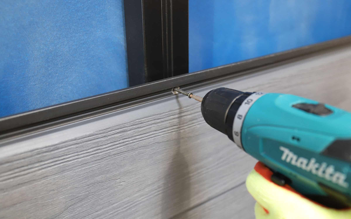
Pre-drill the composite joists before fixing to reduce the risk of cracking. The supplied method recommends countersunk A4 stainless steel screws, but the complete anchoring arrangement must be selected for the wall and installation conditions.
Follow the approved fixing specification, checking alignment as you work. Do not use tightening force to pull a joist across an unsupported void or distort it against an uneven wall.

Step 5: Inspect Before Covering the Frame
Once the frame is secured, check the centres, joints, perimeter support and cavity. Correct missing supports or alignment issues now, while the wall fixings remain accessible.
Photograph the completed framework and retain the product instructions and fixing details with your project records. This gives you a useful reference once the boards are fitted.

Common Subframe Installation Mistakes to Avoid
- Measuring the wrong gap: batten centres are measured from the centre of one support to the next.
- Missing board-end supports: plan butt joints before fixing the battens.
- Blocking ventilation: review horizontal obstructions, trims and opening details as part of the cavity design.
- Confusing membrane types: use the specified layer in its intended position.
- Using a generic wall screw: match the anchorage to the substrate and loads.
- Ignoring uneven backing: check the finished plane across the whole frame.
Composite Cladding Subframe Installation FAQs
Can Cladding Boards Be Fixed Directly to the Wall?
The NeoTimber® system requires a suitable subframe. It provides the fixing supports and space behind the boards needed by the installation.
Are 500 mm Centres Suitable for Every Project?
No. They are the maximum centres stated in the referenced guidance. Product requirements, exposure and the designed fixing arrangement may call for closer supports. Confirm the specification for your installation.
Does Vertical Cladding Need a Different Frame Layout?
It can. The supports must receive the board fixings while maintaining a drainage and ventilation route. Confirm the full arrangement rather than simply rotating the battens.
Are Joist Expansion Gaps the Same as Board Gaps?
No. The joist end gap applies to the framework. Cladding board joints have their own requirements, which should be checked in the applicable installation instructions.
Get the Framework Right Before Fitting the Boards
A well-planned frame brings board support, alignment, ventilation and fixing design together. Confirm these details before you begin covering the wall, then follow the instructions for fitting your chosen cladding and trims.
Explore the NeoTimber® installation resources, or contact the team for clarification on your cladding and subframe components.